
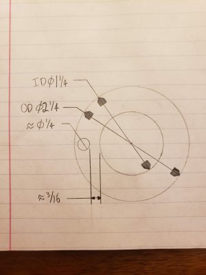
I can't take a picture because the bearing and some roller bearings from an Atlas counter shaft are currently taking a bath in some lacquer thinner. But here is a sketch of about how it looks there is plenty of room for a "keyway" with just the problem of getting it machined in there. Can you single point broach with a carbide grooving tool in the quill of a mill similar to the hobo way to broach keyways into pulleys with HSS??? or grinding, but then that leaves abrasive. Maybe a small carbide end mill, doesn't have to be a square, just needs to be clearance, or by hand with a carbide burr. Not sure if that would be any better than the abrasive. Don't have any experience with carbide burrs so I'm not really sure.

-
Welcome back Guest! Did you know you can mentor other members here at H-M? If not, please check out our Relaunch of Hobby Machinist Mentoring Program!
You are using an out of date browser. It may not display this or other websites correctly.
You should upgrade or use an alternative browser.
You should upgrade or use an alternative browser.
Upgrading Thrust bearing
- Thread starter timpet98
- Start date
- Joined
- Dec 25, 2011
- Messages
- 10,510
OK, then pulling it out with a pair of pliers or drilling and tapping it for a puller screw may be the only way. You might try heating the opposite side of the spindle with a heat gun and after you have the spindle hot, applying an ice cube to the pin. Or spraying it with freeze spray. And then pulling on it. You would need a stand for the spindle for that as otherwise you don't have enough hands.
I would almost bet that the bore is too hard to cut with a broach. Or for that matter with a carbide cutter. Grinding would work except that the best that you could do is to end up with a semi-circular groove when you need a square one. The only right-angle head and cutters that I know of that might be small enough would be dental equipment. Too expensive. The only practical way that I can think of would be EDM (Electric Discharge Machining) equipment.
I would almost bet that the bore is too hard to cut with a broach. Or for that matter with a carbide cutter. Grinding would work except that the best that you could do is to end up with a semi-circular groove when you need a square one. The only right-angle head and cutters that I know of that might be small enough would be dental equipment. Too expensive. The only practical way that I can think of would be EDM (Electric Discharge Machining) equipment.
I don't think that having it squared up would be that important. If it was round it just wouldn't have great engagement, but it doesn't really have to, the alternative is no pin so thats no engagement all it needs to do is clear the pin no matter what shape it is. Ill as the guys at the mill department at work tomorrow, about machining bearing races. I'm aware of EDM, but also aware of how much it might cost to have it send it out, EDMed and shipped back.
- Joined
- Dec 25, 2011
- Messages
- 10,510
Assuming that you or whomever does the grinding has a way to hold both the bearing and the grinding wheel and that the grinding wheel is the same diameter as the pin, then you could set up and grind a slot whose center was flat out at the height of the pin and whose left and right sides were radius'ed from there back to the ID of the bearing. You would of course have to hold the bearing such that the inner race couldn't move. I would expect it to require several of the grinding wheels to finish.
Well I just caved and decided to file down the pin with a file with safe edges. I attempted to remove it, and it ended up pretty mangled. The bearing is in and everything is back together. I tightened the pre-load nut as good as much as I thought was possible without it locking up. I just had some 20wt oil in the bearing, and it was a bit loud I only ran it for the short time in the videos. The top portion of the babbitt bearing cap is slightly smaller in width than the babbitt in the main spindle casting, I am not sure if this is how it was from the factory, or if it was due to wear. When I had it pushed slightly forward and had a gap on the side of the spacer/gear/pre-load nut there seemed to be more friction due to the spacer only bearing on half of its diameter. So I decided to push it back and I was able to tighten the pre-load nut slightly more and now have a very low amount of end play. The only problem is that now the thrust bearing is only bearing on the babbitt over half of its diameter and now it slips some times. I think If I measure the gap with feelers and place a brass shim I could increase the friction on the bearing side and keep it from spinning. I wasn't sure what the appropriate lubrication was, and I didn't want to pack it full of grease and then have to soak it in a solvent again to remove it from the balls.
How can I post videos? It says that the files are too large, so I tried to put them in a zip folder and it says that it is too big to post. Let me know how to upload videos so you can hear the sound of the bearing
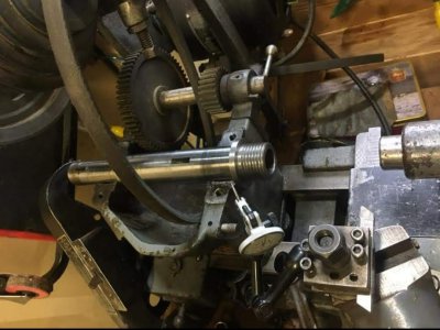
Also I found someone on a facebook group that had just gone through the babbitt headstock of their Atlas 10" to get the play out of it. I noticed that he also had the stamped steel change gear cover that was only on the 1935-1936 models. I asked them if they had had a ball thrust bearing or just a steel spacer and surprisingly he just had a steel spacer similar to my lathe. I remembered how you didn't have parts lists/diagrams for the 101.07306x models without back gears. While his did have back gears, it was of the same generation as mine, so I wonder if the ball thrust bearing might have been something that was added with the update in 1937 when they cast change gear cover, and reinforced tailstock were added. Here is the pic from his facebook post.
How can I post videos? It says that the files are too large, so I tried to put them in a zip folder and it says that it is too big to post. Let me know how to upload videos so you can hear the sound of the bearing
Also I found someone on a facebook group that had just gone through the babbitt headstock of their Atlas 10" to get the play out of it. I noticed that he also had the stamped steel change gear cover that was only on the 1935-1936 models. I asked them if they had had a ball thrust bearing or just a steel spacer and surprisingly he just had a steel spacer similar to my lathe. I remembered how you didn't have parts lists/diagrams for the 101.07306x models without back gears. While his did have back gears, it was of the same generation as mine, so I wonder if the ball thrust bearing might have been something that was added with the update in 1937 when they cast change gear cover, and reinforced tailstock were added. Here is the pic from his facebook post.
Attachments
- Joined
- Dec 25, 2011
- Messages
- 10,510
Well, all that I can tell you is that I do have the Sears Parts Direct parts list for the 101.07360 and it shows the thrust bearing as being 10D-61. However, although I don't recall the details of which part or parts it was, I vaguely recall a few cases where in a later model a revised part was used and the Parts Direct parts list shows the later part as being the available replacement in the earlier machine.
I/we have the parts list for the Metalcraft (Sears version) of the 9". And it calls for a 9-89 Spindle Thrust Washer. So it is possible that the 10" prior to the 10D had a thrust washer either 10-89 or 10-61. And after it was replaced in the 10D by the 10D-61 Thrust Bearing, the thrust bearing became the replacement part for the earlier thrust washer.
To answer your other question, the lubricant to be applied to the thrust bearing would be SAE 20 ND. And the end float that is adjusted by turning the threaded collar on the left end of the spindle should be zero+. Or in other words, no preload.
I don't know why there are no early parts lists for the 10" or 12". We are I guess lucky to have the ones from Parts Direct, even if they do leave some questions unanswered.