- Joined
- Feb 2, 2014
- Messages
- 1,056
I just can't stop making these model engines as this is my fifth to date in less than a year.
I tell my self this is the last one but they are very addictive.
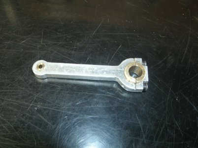
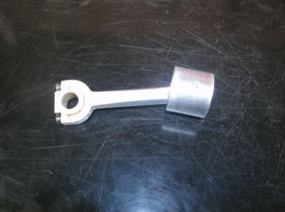
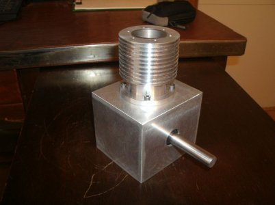
When I started the twin a few months back I had some issues with the crank shaft in fact I had to make three before I got one that I liked. I was looking at one of the rejects the other day and thought I could make a good single cylinder crank from the pieces.
Here are the results.
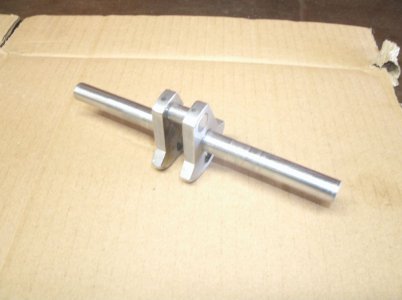
It turned out very nice and too good to just sit on the shelf so I thought I should put it to use.
I don't have a plan or even know what it will look like yet, but pieces keep showing up on my bench.
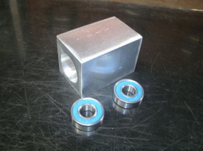
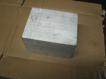
This chunk of aluminum was setting there in the raw material area and it looked like it wanted to be the crankcase.
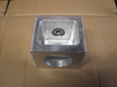
This is it hollowed out with a crank shaft bearing installed and a 2" hole in the other.
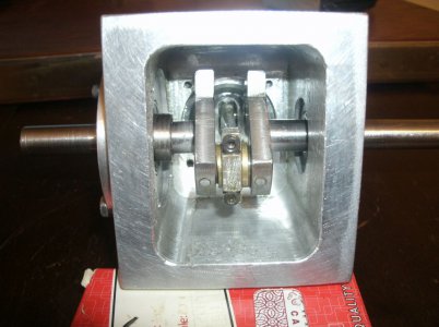
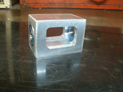
I found an aluminum scrap that wanted to hold the other crank bearing.
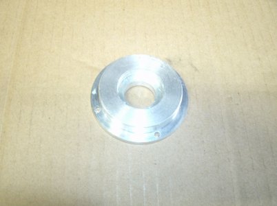
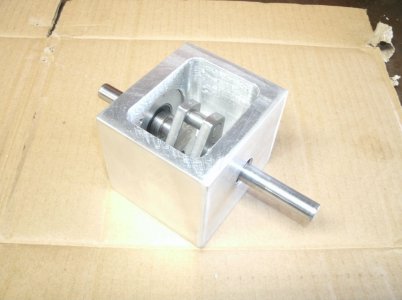
Here they are all together and happy.
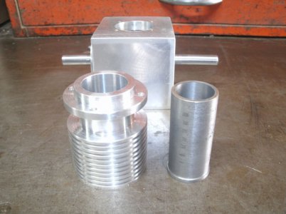
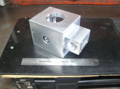
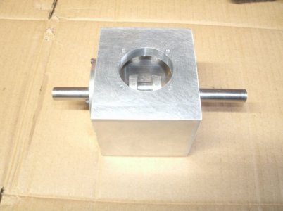
There has to be a cylinder opening so I put it here along with some mounting screw holes as long as I had it setup in the mill.
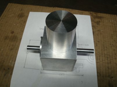
Now this guy showed up so I will have to do something with him.
Maybe a cylinder.
Comments welcome.
Thanks for looking
Ray
I tell my self this is the last one but they are very addictive.
When I started the twin a few months back I had some issues with the crank shaft in fact I had to make three before I got one that I liked. I was looking at one of the rejects the other day and thought I could make a good single cylinder crank from the pieces.
Here are the results.

It turned out very nice and too good to just sit on the shelf so I thought I should put it to use.
I don't have a plan or even know what it will look like yet, but pieces keep showing up on my bench.
This chunk of aluminum was setting there in the raw material area and it looked like it wanted to be the crankcase.

This is it hollowed out with a crank shaft bearing installed and a 2" hole in the other.

I found an aluminum scrap that wanted to hold the other crank bearing.

Here they are all together and happy.

There has to be a cylinder opening so I put it here along with some mounting screw holes as long as I had it setup in the mill.

Now this guy showed up so I will have to do something with him.
Maybe a cylinder.

Comments welcome.
Thanks for looking
Ray


