Vertical IC engine

I made and installed the cam shaft (less the cams) in the housing to determine the distance between centers of the cam and crank shaft.
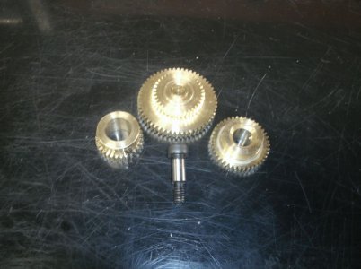
In order to use just two timing gears the cam gear would be over 3" in diameter. It would stick way out over the side of the engine and be in the way of other things. Besides it would look awful so I decided on a double reduction gear train.
The gears are not shown in any order and two of them will be locked together on a single axle.
Tomorrow I hope to have them mounted and meshing nicely.
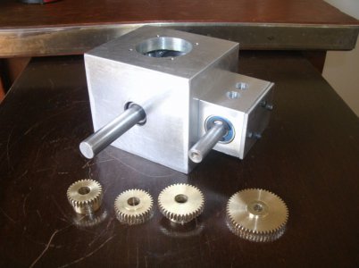
GEDC5084s.jpg

Thanks for looking

Ray
 
Thanks all
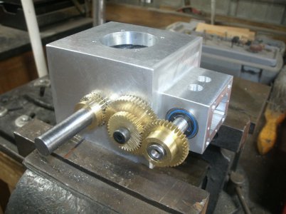
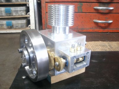
I got the center reduction gears pressed onto the center bushing and assembled all the gears on the engine.
GEDC5087s.jpg

GEDC5093s.jpg

I have one place on every other revolution of the crankshaft that has a slight catch in the gears. I am sure it will work itself out with a little bit of running.
The gear ratio came out exactly 0.5 to 1 like it should with 30/54 teeth and 36/40 teeth.

Thanks for looking

Ray
 
How are you keeping the cam shaft from moving in or out?
 
The cam shaft is captured by the rear bearing with a C clip on the outside and the shaft being larger on the inside. The bearing is pressed into the housing and with little side thrust on the shaft it should work fine.

Ray
 
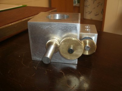
The catch in the timing gears did not work itself out but I did find the culprit. The crank shaft gear had some teeth that were not cut deep enough after the shaft set screw was tightened. I was able to set everything back up on the mill and locate the cutter in just the right place to be able to recut the teeth. I thought I would have to make a new gear but it worked out fine.
I flipped all the gears over from the way I had mounted them the other day and this made for a more compact setup.
I also cut the end off of the cam shaft for the same reason.

GEDC5098s.jpg

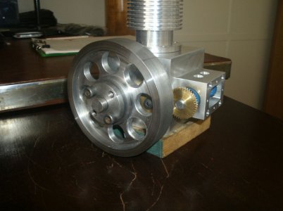
I had a chunk of 4 1/2" round steel about an inch thick so after many hours here is the result.
GEDC5096s.jpg

I made a taper lock bushing for the center which means there are no set screws and repositioning the crank is easy. The taper really grabs the crankshaft with out making any marks.

Thanks for looking.

Ray
 
Did you make flywheel on CNC or the old fashioned way.
 
All was done on manual machines.
Maybe some CNC work tomorrow.

Ray
 
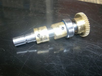
Here is a photo of the cam shaft with the cams close to where they will be positioned for running. I clocked the set screws so that the cams could be adjusted through the side plate hole for final setting.
GEDC5102s.jpg

I made and installed the lifter guides and the lifters.

GEDC5103s.jpg

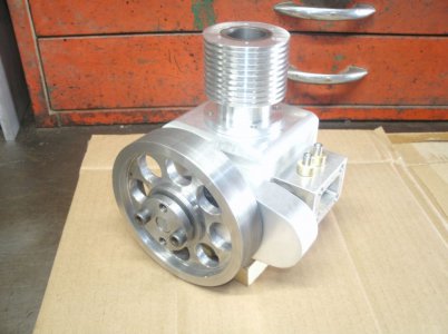
A timing gear cover was made to protect the gears and my fingers. It would have been easy to get something caught in them if uncovered but it does mean the brass gears are hidden.(pity)
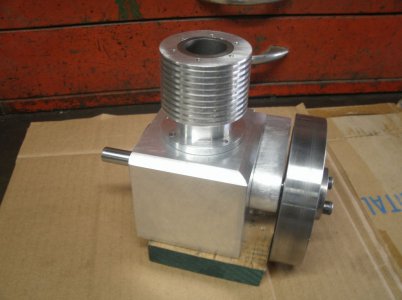
Also did some sculpting work on the engine block to smooth out the lines.

GEDC5109s.jpg

GEDC5111s.jpg

I want to make a base for the engine to get it up in the air a little.
Any suggestions?

Thanks for looking
Ray
 
Back
Top