-
Welcome back Guest! Did you know you can mentor other members here at H-M? If not, please check out our Relaunch of Hobby Machinist Mentoring Program!
You are using an out of date browser. It may not display this or other websites correctly.
You should upgrade or use an alternative browser.
You should upgrade or use an alternative browser.
Vertical IC engine
- Thread starter rdean
- Start date
- Joined
- Feb 2, 2014
- Messages
- 1,055
That was fast francist but I should have been a little more specific.
The engine will have a removable oil pan plate on the bottom so nothing can cover it.
The crankshaft ends of the block are out as I have other plans for them. That just leaves the sides to attach to.
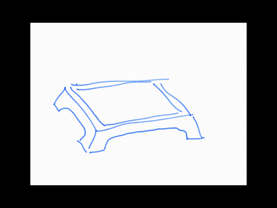
Maybe something with sweeping curves that can be screwed down to a wooden plate?
Ray
The engine will have a removable oil pan plate on the bottom so nothing can cover it.
The crankshaft ends of the block are out as I have other plans for them. That just leaves the sides to attach to.
Maybe something with sweeping curves that can be screwed down to a wooden plate?
Ray
- Joined
- Mar 8, 2015
- Messages
- 307
timing gear cover looks very professional.
- Joined
- Feb 2, 2014
- Messages
- 1,055
Robert
With the cam shaft in place I took a magic marker and made a mark next to the bearing on the shaft. That is not very professional or accurate but it does give me a place to start. If the fit was too tight I would take it back to the lathe and move the groove over a little and try again. If it was too loose I could install a shim on the cam shaft behind the C clip.
As it happened I ended up with about 0.005 end play on the cam shaft first try. I got lucky!
I have decided on the mounting brackets for the engine and simple can be the best solution.
I also painted the engine block to see how things would look.
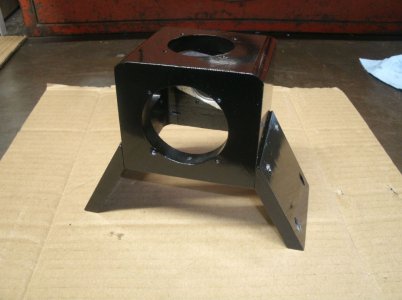
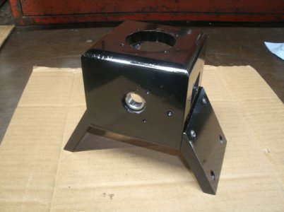
I then noticed that the flywheel was starting to get some rust on it so I painted it too.
I am not sure if it will stay a gold color but my selection of paint on hand was limited. I don't want a white, black, or red flywheel and I am open to other suggestions.
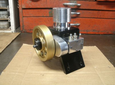
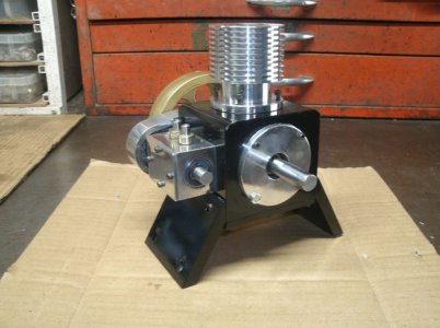
I did a little polishing on some of the aluminum bits too.
Thanks for looking
Ray
With the cam shaft in place I took a magic marker and made a mark next to the bearing on the shaft. That is not very professional or accurate but it does give me a place to start. If the fit was too tight I would take it back to the lathe and move the groove over a little and try again. If it was too loose I could install a shim on the cam shaft behind the C clip.
As it happened I ended up with about 0.005 end play on the cam shaft first try. I got lucky!
I have decided on the mounting brackets for the engine and simple can be the best solution.
I also painted the engine block to see how things would look.


I then noticed that the flywheel was starting to get some rust on it so I painted it too.
I am not sure if it will stay a gold color but my selection of paint on hand was limited. I don't want a white, black, or red flywheel and I am open to other suggestions.


I did a little polishing on some of the aluminum bits too.
Thanks for looking
Ray
- Joined
- Mar 25, 2013
- Messages
- 4,613
Thanks! I have used the same Sharpie technique with mixed results.
I have to say, this is beautiful but I like it better unpainted. The aluminum looks great. It would be pretty cool to nickel plate the flywheel. It is such a beautiful engine I think it is worth the trouble.
Robert
I have to say, this is beautiful but I like it better unpainted. The aluminum looks great. It would be pretty cool to nickel plate the flywheel. It is such a beautiful engine I think it is worth the trouble.
Robert
- Joined
- Mar 8, 2015
- Messages
- 307
Looks good. Hope to see it in person soon.
- Joined
- Feb 2, 2014
- Messages
- 1,055
I apologize for not taking many pictures lately but I have made some progress.
I completed the cylinder head, valves, valve guides, and installed the spark plug.
I cut cooling fins around and on the top of the cylinder head.
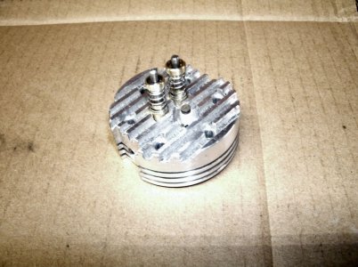
This shows the under side of the head.
As you can see the valves are not centered up and down in the head. They were raised up 0.130 from the center line to allow for more room for the spark plug socket hole. That little plug is way down in there.
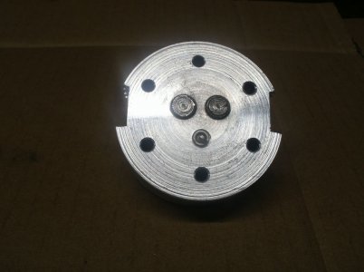
Starting to come together.
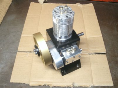
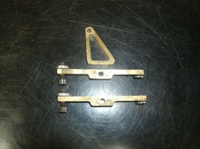
Today I cut out the rocker arms and the rocker arm stand. The stand will be attached to the head by one longer head bolt. This has worked well for a previous build.
I also set the valve timing for startup and made two push rods.
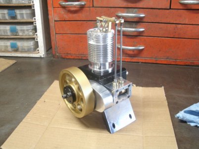
I am still unsure about a fan blade for cooling. I received a nice little 2" diameter blade but even with a shroud around the blade it didn't blow much air. I have a 3 1/2" blade that does move a good amount of air but it seems a little too big and would create more issues.
I will just have to study on it for a while and maybe something will hit me.
Thanks for looking
Ray
I completed the cylinder head, valves, valve guides, and installed the spark plug.
I cut cooling fins around and on the top of the cylinder head.

This shows the under side of the head.
As you can see the valves are not centered up and down in the head. They were raised up 0.130 from the center line to allow for more room for the spark plug socket hole. That little plug is way down in there.

Starting to come together.

Today I cut out the rocker arms and the rocker arm stand. The stand will be attached to the head by one longer head bolt. This has worked well for a previous build.

I also set the valve timing for startup and made two push rods.

I am still unsure about a fan blade for cooling. I received a nice little 2" diameter blade but even with a shroud around the blade it didn't blow much air. I have a 3 1/2" blade that does move a good amount of air but it seems a little too big and would create more issues.
I will just have to study on it for a while and maybe something will hit me.

Thanks for looking
Ray
- Joined
- Mar 8, 2015
- Messages
- 307
Really coming together.
- Joined
- Feb 2, 2014
- Messages
- 1,055
I ordered another fan today. It is 3" in diameter and is rated at 65CFM at 3000rpms. Now I just have to figure out how to squeeze it into the design.
I went a different route today and made the gas tank. It has plexiglass ends so I can see how much gas is in the tank and it is 1 1/2" long and 1 1/4 " round.
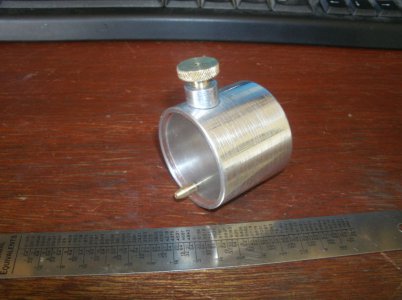
Robert I didn't paint it but I was tempted.
Thanks for looking
Ray
I went a different route today and made the gas tank. It has plexiglass ends so I can see how much gas is in the tank and it is 1 1/2" long and 1 1/4 " round.

Robert I didn't paint it but I was tempted.
Thanks for looking
Ray


