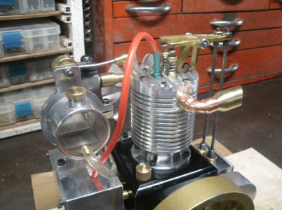
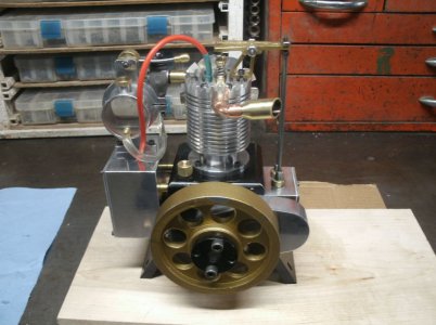
Vertical IC engine

I used some gasket sealant on the gas tank and it must be working as no leaks after 24 hours.

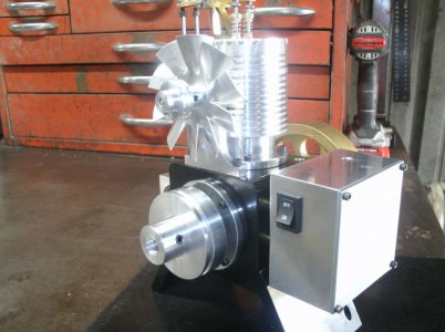
Still waiting on the fan blade to come in so I will move on to the electronics box. This box will house the batteries, the ignition module, and the on/off switch.

I started with a solid chunk of aluminum of about the right size.
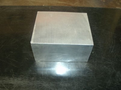
GEDC5144s.jpg

After milling and trueing all the sides it ended up 2.900 X 2.900 X 1.75 deep and a medium pile of chips.
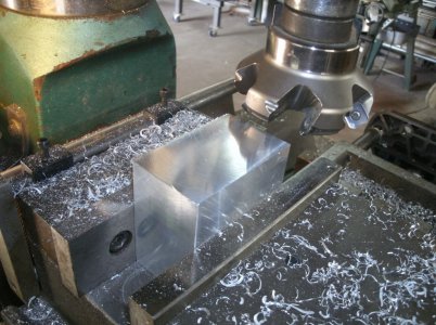
GEDC5146s.jpg

I then milled out the inside of the box leaving 0.125 thick side walls and the same on the bottom.
A mountain of chips all over the place.
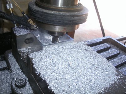
GEDC5148s.jpg

2 hours later and here is the result.
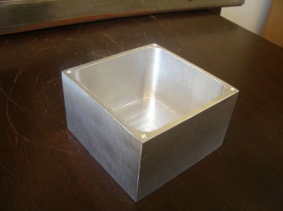
GEDC5157s.jpg

Probably the nicest box I have ever made and it is even the right size for the components.
I still have some holes to make for the ignition wire, the hall sensor, the on/off switch, and the mounting bolts. I was going to mount the box on the side of the block but now I think I will use some spacers to get it away from some of the heat.

Thanks for looking
Ray
 
Sweet. I am very interested in seeing how the ignition works.
Robert
 
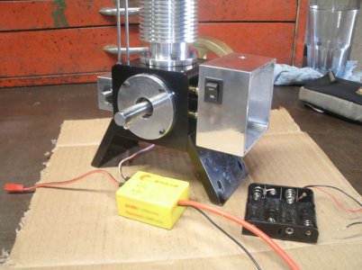
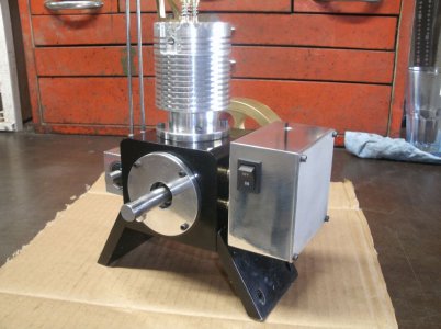
I cut a hole for the on/off switch, polished, and mounted the electronics box using brass standoffs.

GEDC5160s.jpg

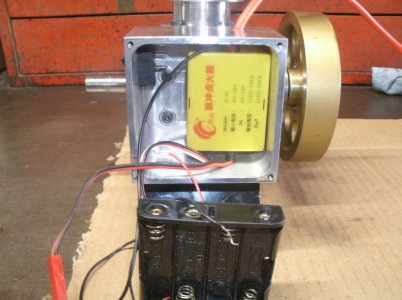
The ignition module and the battery holder fit nicely inside.

GEDC5162s.jpg

The cover I made was of some other aluminum alloy and would not polish up like the rest of the box did.

GEDC5163s.jpg

I have had good luck with this type of ignition module in the past and have used it on two other engines. There are several manufactures that make similar modules for model airplane engines and I have used some of those as well but they cost much more. The battery holder holds 4 AA batteries and they do last quite a long time.
Robert I will show the hall sensor, magnet and spark plug later on in the build.

Thanks for looking
Ray
 
I turned a couple of brass pieces for the carburetor and checked the fit.
GEDC5165s.jpg

Well it looks OK but that won't work as it is in the road of the fan so I will have to redo it later.
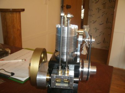
I also cut a mounting bracket for the fan and the driven pulley. The bracket has two ball bearings on the shaft.

GEDC5167s.jpg

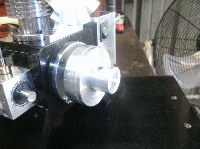
This is the crankshaft pulley and it has three functions. First it has a magnet sunk in to the side toward the engine for the hall effect sensor. The pulley groove will turn the fan and the hub can be used for a flat belt or a V belt for power transfer.

GEDC5172s.jpg

This is a better picture of the fan mount with the belt installed.

GEDC5178s.jpg

Thanks for looking
Ray
 
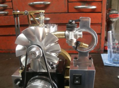
Made a longer manifold for the carburetor to move it out of the way of the fan.

GEDC5183s.jpg

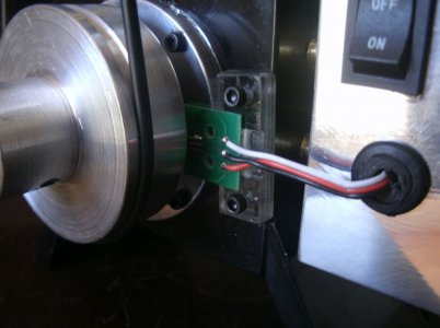
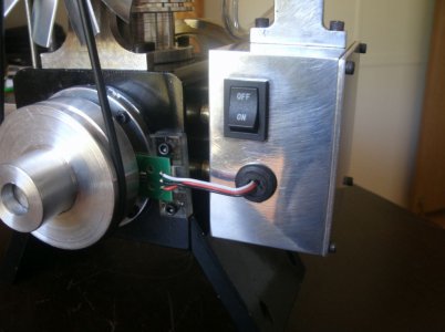
I glued the hall sensor circuit board to a piece of plexiglass and screwed it to the block.

GEDC5193s.jpg

The ignition timing will be adjusted by adjusting the belt pulley on the crankshaft.
I even put a grommet in the hole for the sensor wires.

GEDC5194s.jpg

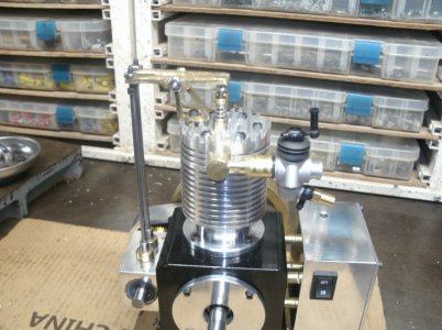
The arm with the brass ball on the end is the throttle and it raises and lowers the barrel in the carburetor.
I also finished the electrical wiring and installed the gas line.

GEDC5196s.jpg

Just a couple of small items left to do and then we will see if it will run.
And I should make a mounting board to screw the motor down to as I don't want to chase it across the bench.

Thanks for looking
Ray
 
That is a thing of beauty.
R
 
Thank you Robert

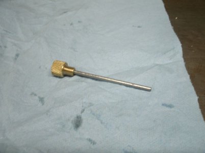
Today I made a dip stick so I could check the oil level. Brass knob with a 1/8" rod cut just shorter than the bottom of the engine. It is really hard to see the level on the stick of the new oil.
Any suggestions as to what color I could paint the stick to make it more visible?
GEDC5204s.jpg

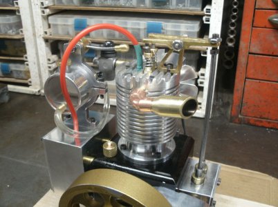
A couple of shots of the exhaust system. I am not sure I like the size of the exhaust pipe as it looks out of place. I will think about making one similar from 1/2" stock instead. The copper elbow is another point I am not sure if I like it.
What do you think? Give me some ideas.

GEDC5201s.jpg
GEDC5202s.jpg

I found a piece of maple to mount the engine on and I left it longer and unfinished at this point. I may want the engine to run something so I will need the extra length for that.
Any ideas? Maybe a pump, a butter churn, or a generator.

GEDC5207s.jpg

Oh almost forgot:

IT RUNS!!

I didn't plan on starting the engine today but I had everything hooked up and with oil in the engine why not put in some gas and give it a spin or two. Maybe it will give me a couple of pops. Well to my surprise it started right up and ran for about 15 seconds. I was too shocked to adjust anything the on the first run I just stood there watching.
I did adjust he timing a little and some on the carb during the next few runs but running time was getting less each try.
I noticed that there was an oil leak from the cam bearing opposite of the timing gears. I have not yet installed a crankcase vent so hopefully that will stop the oil leak.
I also found that the compression was noticeably lower than when I started. I had questioned myself as to the o-ring groove depth when I cut it on the piston but decided to try it as it was. I may have to shim under the o-ring to get a better fit.

Thanks for looking

Ray
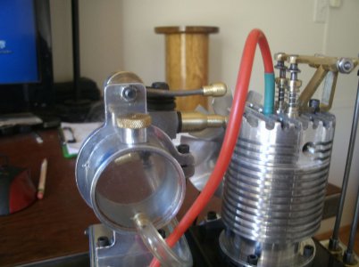
 
Great news. Looking forward to seeing it in person
 
I don't like the copper either. Brass or stainless would be nice.
R
 
Back
Top