-
Welcome back Guest! Did you know you can mentor other members here at H-M? If not, please check out our Relaunch of Hobby Machinist Mentoring Program!
You are using an out of date browser. It may not display this or other websites correctly.
You should upgrade or use an alternative browser.
You should upgrade or use an alternative browser.
Vevor 250 x 750 Lathe Upgrades
- Thread starter lesrhorer
- Start date
Phase III: QCTP
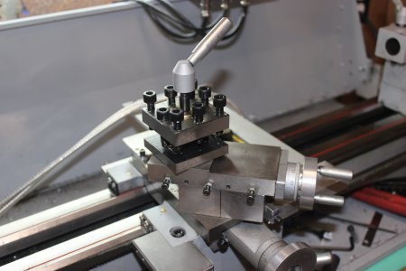
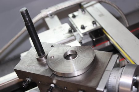
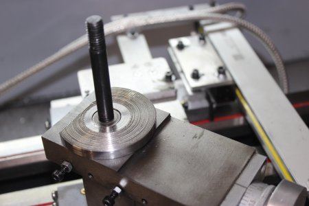
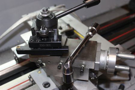
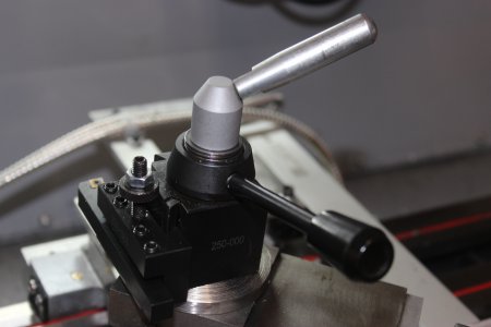
The lathe came with a classical square turret tool post. Now, there is nothing particularly wrong with those posts, and they certainly have excellent rigidity, but unless one is engaging in a very limited set of operations on the lathe, the Quick Change Tool Post is certainly far easier and faster to swap out and set up tools on the lathe. Given the relatively low cost and very decent quality of Aloris clone tool posts, I would say it is, if not quite essential, at the very least a highly desirable and economical upgrade for the lathe. Swapping out the tool post is fairly easy. The hold-down bolt for the square tool post is usually too short, so the first step is to remove it from the compound and replace it with the one supplied with the new tool post. The QCTP may come with a thick spacer to fit between the post and the compound. Its use may or may not be necessary. In my case, it was, but the spacer did not fit my lathe. Rather than modify the spacer, I made a new one from cold-rolled steel. The post tended tor slip on the spacer, so I roughed up the surface of the spacer so it no longer slips. There is a small indexing post on the compound, so I drilled a small divot in the bottom of the spacer to accomodate the indexing post. This insures the spacer does not slip on the compound. I made the spacer of round stock, but a couple of the tool holders, notably the parting tool, need to slide down further than the spacer allows. I milled off one side of the spacer to allow the holder to sit all teh way down on the compound when necessary.
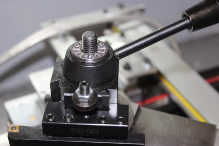
When tightening down the tool post at a required angle, there is a tendency for the post to slip as the nut is cinched down. A simple flat washer caqn help alleviate this, but a thrust bearing will help even more. I purchased a thrust bearing off Amazon for $3 - hardly a difficult purchase. The thrust bearing with its two included flat washers not only completely eliminates any tendency of the post to move when tightening it down, it also allows the original locking lever that came with the square tool post to be used. Without the thrust bearing, the bolt was just a little too long to allow the lever to be used, meaning one had to use a plain hex nut with a separate wrench to cinch down the post. The permanently attached lever is far more convenient.
Phase IV: Chip Shield
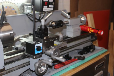
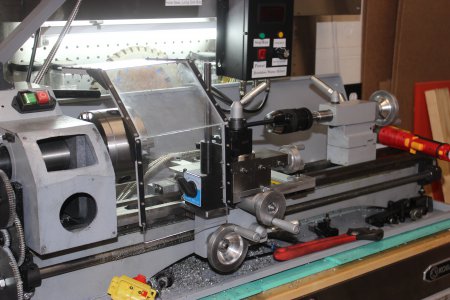
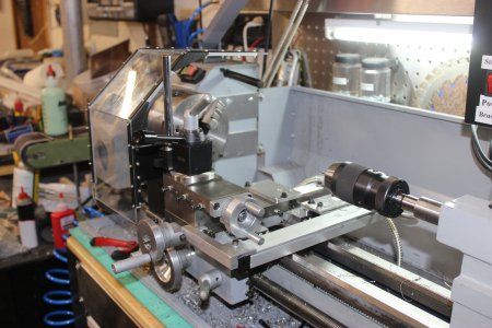
I previously posted the plans for this guard here. Machining on the lathe or mill tends to cast swarf all over the shop, including in my face and down my shirt. This helps. I machined a small shelf out of mild steel and attached it to the left side of the carriage to make it more convenient to attach the magnetic base and position it over the chuck. It can also attach to the compound.
I previously posted the plans for this guard here. Machining on the lathe or mill tends to cast swarf all over the shop, including in my face and down my shirt. This helps. I machined a small shelf out of mild steel and attached it to the left side of the carriage to make it more convenient to attach the magnetic base and position it over the chuck. It can also attach to the compound.
Phase V: Carriage Handwheel
The carriage handwheel on this lathe is quite unacceptable. It wobbles badly, causing the movement of the carriage to be very jerky as the friction betwen the wheel and the carriage body jumps up and down wildly. Furthermore, the handwheel handle is very short and thin. This means it is a bit uncomfortable to grasp, and since the wheel is quite close to the cross slide handwheel, it means my fingers often hit the cross slide wheel handle.
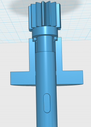
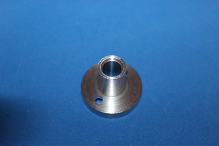
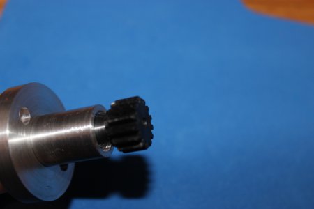
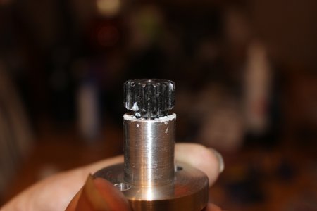
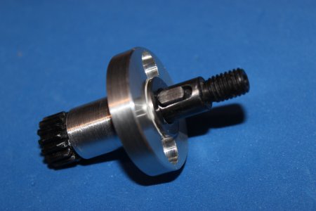
Job 1 is to add a pair of thrust bearings to the wheel and tighten the wheel on the axis. There are a couple of hitches, however. The first is the handwheel assembly fits through a 16mm hole in the carriage, while the axle is 10mm. Obviously, the thrust bearing on the inside of the carriage housing next to the drive gear cannot be more than 16mm in outer diameter. I looked rather extensively, but rather unsurprisingly I was unable to find a 10mm x 16mm thrust bearing. I decided to manufacture the bearing right into the handwheel assembly itself. I purchased some 2mm ball bearings, and turned down the shaft near the drive gear by 2.2mm. I then bored out the body to a depth of 1.8mm and a diameter of 12mm. I placed 18 ball bearings down inside the body next to the shaft.
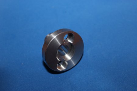
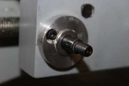
On the other end of the shaft, there was not quite enough room between the body and the Woodruff key to accommodate the outer thrust bearing, so I faced off the body by 1.5mm. Unfortunately, after this was done, the recessed retaining screws stuck up above the body, interfering with the placement of the bearing, so I used an end mill to bore the counter-bore down by another 1.5mm. The hand wheel stuck out a little more than I liked, so I bored an 18mm hole 3.5mm deep in the body to accommodate one of the thrust washers and the bearing, leaving 2mm of the thrust bearing assembly protruding from the body.
Last edited:
- Joined
- Oct 14, 2013
- Messages
- 981
A fun mod! The light loads should play well with the un-hardened surface.
Sent from my SM-G892A using Tapatalk
Sent from my SM-G892A using Tapatalk


