VFD Wiring Help?!

FANTASTIC! Such joy when it works.

I suggest you look into a pot to control VFD speed as your next action item. Even if you have multiple speeds with gearing, this addition is SO HANDY.

Next look at getting a braking resistor. the lathe will take forever to spin down from high speed. this solves that issue.

Have fun!
 
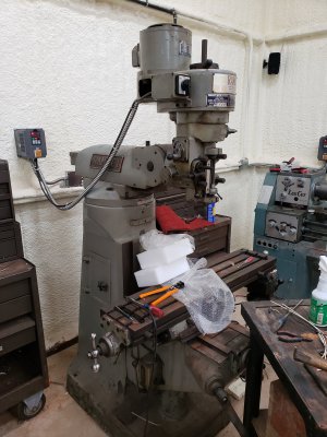
Mill hooked up and running as well! I do have a question: is there a way to program the vfd to show actual spindle speeds? If so, what parameters an I looking for to program, or what method to use? Thanks for all the help!
 

Attachments

  • 20200711_110311.jpg
    20200711_110311.jpg
    2 MB · Views: 12
Which brand VFD? Most have this.
 
don't have that manual handy, sorry. if you are good at decoding their chinglish, I bet its in there. It would be under the display settings parameters.
 
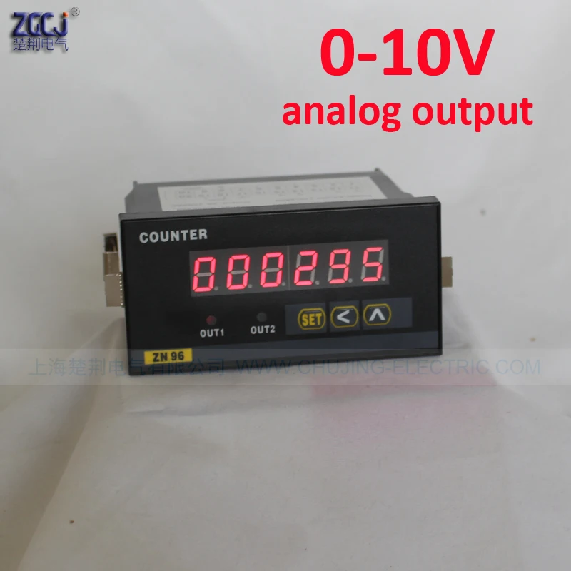
You can display either motor Hz or Motor RPM, there is an indicator light for each. How you get it to cycle to RPM and use that as a default is a mystery to me, I assume you use the up down buttons to scroll through the functions. Others VFD's you can set a scaling function and a default display value, so you can account for the final fixed drive ratio. An alternate that is often used is the output terminals (AM, ACM) of the digital frequency which gives a 0-10V/10mA voltage swing, this is used with a digital voltmeter that can be scaled to give a numeric RPM value. This is commonly used with factory VFD 2 speed mills and lathes, the voltmeter has two inputs, each input is sclaed for the respective range and uses a switch to switch inputs when the gear is changed. So a bit more complicated and you need a separate power source for the meter. Some of the RPM voltmeters have 2 inputs, each scalable, alternative would be use resistors as a voltage divider. The decimal place can also be changed. These types of digital meters can be expensive.

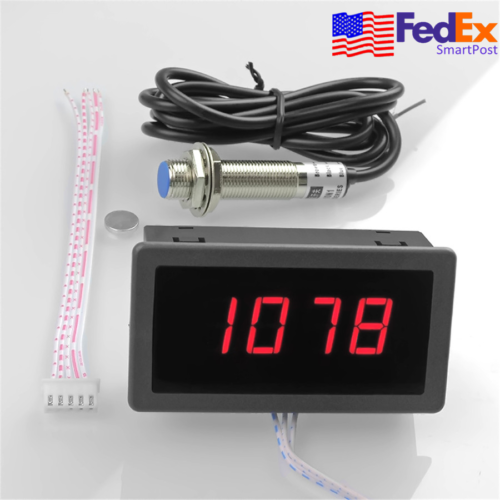
An alternate is to buy an inexpensive tachometer that uses a hall sensor and a magnet, about $15-20, the magnet needs to be mounted somewhere on the spindle. You need a small power source for the tach, usually 12VDC. Another option is to use a hand held tach for ~$20, and take a quick read of the spindle. You could also make a chart for the speed in each belt ratio and scale the value based on the Hz reading.
 
Hi Mark,
I spend a long time looking for a high resolution tach in a small package. $14.00 free shipping from China! I purchased two and they both worked with a Hall effect sensor I purchased separately. I have put one in my PM1440GT front panel, but I will never test out the higher digits!!!

https://www.aliexpress.com/item/32974138466.html?spm=a2g0s.9042311.0.0.27424c4dlY8Cn8 In case the link fails the add title can be searched at AliExpress.com "6 Digits Digital Tachometer Speed Measure Meter"

Below I have copied pasted the add description:

"The tachometer is small,cost-effective.it fit 5-999999 RPM speed motor,it can accurately measure the RPM of the engine and the various motors.
Features & Specifications:
Power requirement:DC 8-15V
Measure range : 5-999999RPM.
Clear zero: Automatic,
Clear zero time: about 10s.the greater the RPM value,the longer the clear zero time.
Refresh frequency: 0.2-0.5S@120-1200RPM;0.25-0.6S@2400-999999RPM.
Measure indication:RPM<5000,±2;RPM>5000,±3.
Display:RED 0.56” LED
Input sign:pusle signal,wet contactor signal,PNP or NPN proximity switch,HALL sensor.
Overall Dimension: 60x29x25mm,
Panel cutout Dimension: 58.5x27.5mm
Operating temperature: 0 to 50°C.

Packaging include:
Tachoneter x 1 (come with 4pin cable)"

Dave
 
Wow!

Not for sure where the smiley faces came from! Embedded in the web page script? I should have pasted the description to notepad and then copied from there!

"Power requirement:DC 8-15V"

"Input sign: Pusle signal, wet contactor signal, PNP or NPN proximity switch, HALL sensor."
 
Back
Top