Voltage reduction of a DC motor

aliva

Active User
H-M Platinum Supporter
Joined
Feb 28, 2012
Messages
1,623
I have a project comining up thats requires the speed reduction of a DC motor.
The motor is from a automotive power window. Its 12 VDC, the measured resistance of the motor is 1.3 Ohms. The RPM is approximetly 100, I need to reduce the rpm, so I have to reduce the voltage to around 6 to 8 volts.
This should reduce the RPM to an acceptable level. The supply voltage is 12 VDC.
As I see it there are a couple of ways to accomplish the voltage reduction, resistor, potentiometer, motor controller or a regulated power supply. I can't use the regulated power supply, as this a mobile project and there won't be access to 120VAC to power the regulator.
I could order a motor controller or potentiometer but the delivery time is an issue. That leaves the resistor route.
My question is what value and wattage resistor(s) would I require?
The full load current draw @ 12VDC I understand would be around 9 amps. The motor will never see that much, as its rotating a chute round 180 degrees of rotation, and the friction is vertually zero. So I will guess the amp draw would be only 1 amp @12VDC. In an AC ciruit when the voltage drops the current rises, I'm not sure if thats applies to DC. If thats to be true the current draw would increase to 2 amps.
I've done some calculations from formulas from the net, the results indicate a resistor value of 1 Ohm. That dosen't seem right to me but it maybe. This is why I require some input from the more experinced. Also I have no idea as to the wattage of resistor needed.
Any assistance would be appriciated
 
Motor resistance changes with load making exact calculation difficult. Using the resistance you gave of 1.3 ohm yields a draw of around 9 amps. That would be the max. If you cut the supply voltage to 6v the current will fall by half (v=IR). So assuming the same load, you would draw 4.5 amps at 6v. The wattage would therefore be 27 watt (4.5 x 6). The wattage through the motor and an inline resistor would be the same. That is a pretty healthy resistor and will get hot! Under no load the current could go down substantially but if the motor gets stalled for any reason the current will max out.

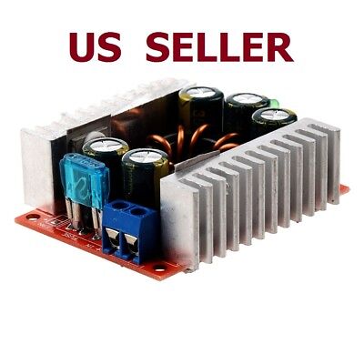
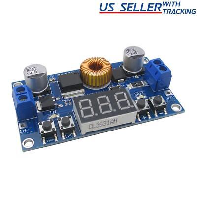
I would try to find a buck converter that can handle the wattage. There are plenty on evilBay.


An adjustable one will also let you dial in the RPM.

The ones with the built in voltmeter are cool!


Robert
 
Last edited:
Most DC motor controls use Pulse Width Modulation (PWM). This outputs the full 12V but chops it ON and OFF very quickly. The duty cycle (% of ON time to OFF time) sets the speed. This is because the average voltage will drop as the duty cycle drops.

I would not try to reduce the voltage with a power resistor or a DC buck supply. These are very inefficient and there is already proven technology designed to drive DC motors.

Here are some from a reputable industrial automation supplier: https://www.automationdirect.com/ad...es/low_voltage_(<_50v)/open_frame/gsd1-48-10c

Amazon (no idea about this product, just did a quick search): https://www.amazon.com/RioRand-7-80...1587999324&sprefix=DC+motor+sp,aps,164&sr=8-5

And another: https://www.amazon.com/Sydien-DC6-9...587999400&sprefix=DC+motor+sp,aps,164&sr=8-18
 
I side with Robert on this, from post #2, the dc to dc buck converters are fairly efficient and much preferable to a simple resistor- the speed regulation will be better too
Mark
 
Yes, you can lower the speed of the motor by dropping the voltage with a resistor or rheostat. However, you would also lose power and torque. Can you instead use a couple of gears or pulleys with a 1 to 2 ratio? The motor will be just fine at 12volts and you will have the lower speed at twice the torque.
 
The elegant ways would be the bucking power supply or a PWM supply. A resistor, rheostat, or potentiometer (all essentially the same device) would be the simple way but they waste powerin the voltage dropping process. Another way would be an LM317 voltage regulator with a power transistor to handle the current. The parts count would be four to six and total cost should be under $3. The only drawback is that you wouldn't be able to apply the full 12 volts.
 
A pulse width driver(PWM) would be the most effective. The PWM will cause some "buzzing". That usually isn't a problem but can matter in some applications. I looked at the recommended drivers listed above. The most effective being the last of the three.
https://www.amazon.com/Sydien-DC6-9...587999400&sprefix=DC+motor+sp,aps,164&sr=8-18
The concern with the output voltage is a non-issue, It will NEVER exceed the input. And no need for a regulated power supply. A basic battery charger would suffice. Even a microwave oven rewound transformer will work with a bridge rectifier. And a battery is the ultimate in smooth.

Simply set the desired speed and seal the pot(entiometer). I usually use fingernail polish. A loud colour is easy to see and being brittle it usually breaks away fairly easily.

An LM317 will work but you would lose a little torque. As you reduce the voltage, you lose not only torque but speed regulation as well. Plus the fact that the difference in power between input(line) and output (motor) must be disipated somewhere(the 317). An LM317 will require a VERY large heat sink. It can provide a very smooth, well regulated output to a known, constant load. But normally is too well regulated for motor drive. There are exceptions with smaller motors, I use them regularly. But something the size of an automotive motor needs a very large heat sink.

Resistance is the oldest and most well known method to old school electricians. It is still used with very large motors. I have worked with DC motors as large as 5000 HP. But at that size, the generators were regulated on output rather than using resistance.

For fractional HP size motors, resistance has fallen by the wayside in favour of duty cycle control for well over 50 years. Motors of a few hundred HP are the largest I have worked with using resistance. Grid resistors are about the size of a case of sodas, 24 cans. And larger. "Watts is watts" and must be disipated somewhere. With resistor control, the resistor is where the extra power is disipated.

BEMF (back EMF) is another subject dealing with motors. I have a web site still up that touches on it.
But only touches, BEMF is a large portion, along with magnetics, of a degree in Electrical Engineering. And I don't think that is appropriate for a message board.

I apologize for waxing so verbose above. The subject is deep and I will expound on the subject for hours if I can.

.
 
Thanks to all that replied. Now I have to digest all of the suggestions and pick a solution.
 
Variable resistances (rheostats) capable of currents of several amps or more are fairly large wirewound affairs. They tend to be costly as well. Mouser lists them at $75 and up. If the rotational speed is fixed, a fixed resistance can be used. The resistance can be adjusted by several means. The way that I would do it is wiring several resistors in parallel. If you estimate the final resistance at 1 ohm, chose a resistance like 1.1 ohms. That can be paralleled with a comparatively larger resistor of 11 ohms to bring the resultant resistance to 1 ohm The second resistor, being 11 x the value, is only carrying 9% of the total current. If you have required current of 5 amps, only .45 amps will be flowing through the second resistor so about 2.5 watts. This can be carried additional steps to fine tune the operation as necessary. If the ratio of the adjustment resistance to the final resistance is high enough, a rheostat/potentiometer can be used for tweaking The equation for the adjustment resistance is Radj = (Rinitial x Rfinal)/(Rinitial-Rfinal) where Rinitial is the initial resistance and Rfinal is the desired resistance.
 
I bought a 12v control that only needs a 12v power source (battery) off of Amazon for about $12. It had a forward/reverse switch, and a pot. I used it to control a 12v door window motor on the lead screw of my first lathe. It worked perfectly.
 
Back
Top