-
Welcome back Guest! Did you know you can mentor other members here at H-M? If not, please check out our Relaunch of Hobby Machinist Mentoring Program!
You are using an out of date browser. It may not display this or other websites correctly.
You should upgrade or use an alternative browser.
You should upgrade or use an alternative browser.
Volvo Amazon 1965 (Volvo 13134)
- Thread starter MrCrankyface
- Start date
- Joined
- Nov 7, 2019
- Messages
- 433
I'm not sure if there's a saying in english, where you're "just gonna fix one thing" and it ends up being a whole list of issues. 
But I was just going to fill part of the huge hole in the backseat wall.
The hole is that huge because I thought the top link was going to sit ontop of the diff housing but later changed my mind.
Mostly I need the structural strength before I cut a new hole right on the side of it for the new placement of the top 3-link.
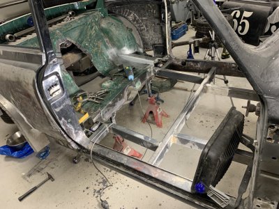
BUT apparently the piece I had saved to fill with, wasn't the whole piece.
I had to measure and 3D-print a press-mold to make the little extra part on the right, then spend several hours welding this up, grinding it flush and carefully adjusting the perimeter to fit well in the backseat wall.
Several hours that could have been saved if I:
-Had not a cut an obscenely large hole in the backseat wall.
-Had not lost the extra piece I now had to remake.
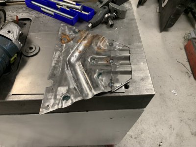
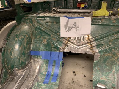
Bunch of hours later I can finally get back to what I was going to do, mark out and cut the hole for the top link...
Pretty daunting to actually cut it, when I've just had to back-track a whole bunch of hours to repair my last mistake.
But I was just going to fill part of the huge hole in the backseat wall.
The hole is that huge because I thought the top link was going to sit ontop of the diff housing but later changed my mind.
Mostly I need the structural strength before I cut a new hole right on the side of it for the new placement of the top 3-link.

BUT apparently the piece I had saved to fill with, wasn't the whole piece.
I had to measure and 3D-print a press-mold to make the little extra part on the right, then spend several hours welding this up, grinding it flush and carefully adjusting the perimeter to fit well in the backseat wall.
Several hours that could have been saved if I:
-Had not a cut an obscenely large hole in the backseat wall.
-Had not lost the extra piece I now had to remake.

Bunch of hours later I can finally get back to what I was going to do, mark out and cut the hole for the top link...

Pretty daunting to actually cut it, when I've just had to back-track a whole bunch of hours to repair my last mistake.

- Joined
- Aug 6, 2015
- Messages
- 3,882
I'm not sure if there's a saying in english, where you're "just gonna fix one thing" and it ends up being a whole list of issues.
Oh yes... the "While I am in there" syndrome. Very familiar with it
- Joined
- Nov 7, 2019
- Messages
- 433
It's honestly both amazing and a bit depressing how fast time flies and nothing gets done.
This time I got stuck(mentally) because I wanted/needed something to easily raise and lower the axle, to help me get it in place while fabricating and later adjusting the links.
Spent hours working on a design I could build myself from scrap and cheap lumber, then lumber prices soared...
Started looking at alternative solutions and my energy just ran out and everything ground to a halt.
I mean sure, I could just put my hydraulic jack under it but it's just not convinient enough, trying to keep it level/occupying the jack from other things, difficult to get just the right height etc..
4 months later, yesterday, I just gave up and decided to buy my way out of this so I can get back to the actual project at hand, working on the car...
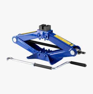
I've ordered two mechanical scissor jacks rated for 2 tons each, going to hook up a geared DC-motor so I can run them both at once and put them under the axle.
Should let me easily move the axle up and down all day to figure out clearances, set mounts in good positions, adjust link lengths and so on.
Basically two of these, most likely with the threaded rods in line with eachother, spaced a meter or so apart to lift on the "axle tubes".
To be continued..
This time I got stuck(mentally) because I wanted/needed something to easily raise and lower the axle, to help me get it in place while fabricating and later adjusting the links.
Spent hours working on a design I could build myself from scrap and cheap lumber, then lumber prices soared...
Started looking at alternative solutions and my energy just ran out and everything ground to a halt.
I mean sure, I could just put my hydraulic jack under it but it's just not convinient enough, trying to keep it level/occupying the jack from other things, difficult to get just the right height etc..
4 months later, yesterday, I just gave up and decided to buy my way out of this so I can get back to the actual project at hand, working on the car...
I've ordered two mechanical scissor jacks rated for 2 tons each, going to hook up a geared DC-motor so I can run them both at once and put them under the axle.
Should let me easily move the axle up and down all day to figure out clearances, set mounts in good positions, adjust link lengths and so on.
Basically two of these, most likely with the threaded rods in line with eachother, spaced a meter or so apart to lift on the "axle tubes".

To be continued..
- Joined
- Nov 7, 2019
- Messages
- 433
A whole lotta work later, or well, mostly brainwork.
Found a suitable 24V DC motor from an old adjustable desk, unfortunately it just had a little nub as a driveshaft.
I took everything apart and luckily it could be pressed out of the gear.
I then machined some 12mm steel to fit in the bushings and gear, to get a output shaft that'd be easier to use.
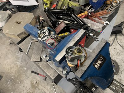
Coupled with milling a long aluminium bar and some 3D-printing and we got this thing.
I wanted to modify the screwjack as little as possible.
The big gear is in 2 parts, the central holder and the gear ring.
The holder simply slips over the regular screwhandle thing, where you'd attach the "normal handle".
I then drilled and tapped two small(M4) holes in the hinge pieces, small enough that it shouldn't affect any structural strength but enough to hold my parts on.
Originally the motor only sat on the screw closest to the gears but this proved a bit wobbly and I added the slotted aluminium bar to hold it aligned at all times.
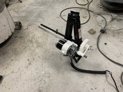
Definitely not fast, this is at it's slowest height though, due to the geometry it moves faster and faster as it goes down.
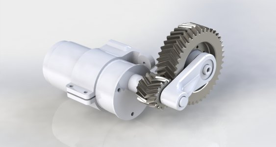
All the prints were printed with "fast" settings ie really weak, this lead to breakage of the gears teeth when I tried lifting my 700kg worktable.
Admittedly probably not the best starting test.
So back to the iterative process.
The teeth are obviously the weakest link so far, partly because of print settings but also because they're plain spur gears, causing a lot of load on one/few teeth.
I'm now working on reprinting most of the pieces in a stronger material(also stronger settings) but to give it the best possible shot I have also increased the gear module, changed to double helical gears, widened the gears and beefed up the link holding/reinforcing the distance between the shafts.
Hopefully this will work so I can start modifying the second screwjack.
Found a suitable 24V DC motor from an old adjustable desk, unfortunately it just had a little nub as a driveshaft.
I took everything apart and luckily it could be pressed out of the gear.
I then machined some 12mm steel to fit in the bushings and gear, to get a output shaft that'd be easier to use.

Coupled with milling a long aluminium bar and some 3D-printing and we got this thing.
I wanted to modify the screwjack as little as possible.
The big gear is in 2 parts, the central holder and the gear ring.
The holder simply slips over the regular screwhandle thing, where you'd attach the "normal handle".
I then drilled and tapped two small(M4) holes in the hinge pieces, small enough that it shouldn't affect any structural strength but enough to hold my parts on.
Originally the motor only sat on the screw closest to the gears but this proved a bit wobbly and I added the slotted aluminium bar to hold it aligned at all times.

Definitely not fast, this is at it's slowest height though, due to the geometry it moves faster and faster as it goes down.
All the prints were printed with "fast" settings ie really weak, this lead to breakage of the gears teeth when I tried lifting my 700kg worktable.
Admittedly probably not the best starting test.

So back to the iterative process.
The teeth are obviously the weakest link so far, partly because of print settings but also because they're plain spur gears, causing a lot of load on one/few teeth.
I'm now working on reprinting most of the pieces in a stronger material(also stronger settings) but to give it the best possible shot I have also increased the gear module, changed to double helical gears, widened the gears and beefed up the link holding/reinforcing the distance between the shafts.
Hopefully this will work so I can start modifying the second screwjack.

Last edited:
- Joined
- Nov 7, 2019
- Messages
- 433
A bit more progress.
Considerably beefier than the first try.
Managed to achieve a good pressfit on all parts as well, had to broach the hole in the white part that sits on the 12mm shaft to get that perfect slide fit.
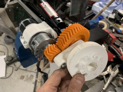
Short video of it.
Lifts my 130kg/286lbs without issues even from the lowest position(it gets stronger the further up it is due to the geometry of the lift).
When trying to lift one side of my ~800kg workbench it just about starts to lift then the powersupply bogs down since it can only supply 300W or so.
Would've been cool if it could lift >800kg for general car work but the 130kg is plenty for what my current use case.
As you can probably see, this thing is no wonder of precision.
The screw itself has both sideways and longidutal movement and is slightly curved, tried to compensate for this by allowing the motor to move with it.
Considerably beefier than the first try.
Managed to achieve a good pressfit on all parts as well, had to broach the hole in the white part that sits on the 12mm shaft to get that perfect slide fit.

Short video of it.
Lifts my 130kg/286lbs without issues even from the lowest position(it gets stronger the further up it is due to the geometry of the lift).
When trying to lift one side of my ~800kg workbench it just about starts to lift then the powersupply bogs down since it can only supply 300W or so.
Would've been cool if it could lift >800kg for general car work but the 130kg is plenty for what my current use case.
As you can probably see, this thing is no wonder of precision.
The screw itself has both sideways and longidutal movement and is slightly curved, tried to compensate for this by allowing the motor to move with it.
- Joined
- Nov 7, 2019
- Messages
- 433
More progress, and brainfarts.
This was the initial idea, where both "handle ends" would be aimed towards each other and driven from the same motor.
The U-joints take up the angular error and the shaft-in-shaft takes up any length error.
What this effectively does is reverse the direction on one jack, so when I try to raise it, one goes down and the other goes up.
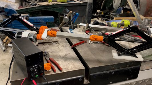
So decided to bite the bullet and disassemble the whole thing and extend the lifting screw so I can rotate it from the right side.
Drilled and reamed 7mm hole in the screw and made the end of this 12mm shaft into a pressfit.
Assembled it without the extension and then pressed it in once the screw was past the nut.
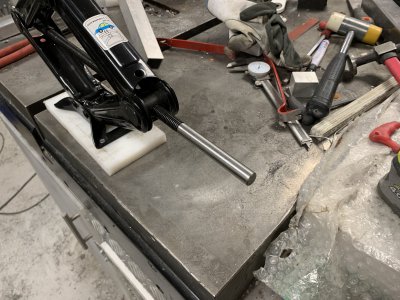
Initial test just to make sure, before shortening the extension, notice the "handle part" is now on the right, outside of the image.
Works as it should now and after I milled a flat on the extension it was perfect.
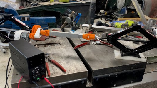
I've done my best to keep this whole thing as low as possible, so I can use it as a universal lifting thing in the future.
This however means it's vastly too low to lift the axle into place, so whipped these extensions together.
I drilled a hole through the red part and the top of the jack so it's possible to secure them.
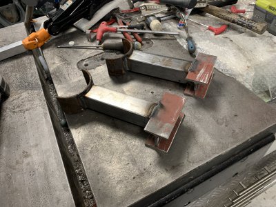
Time for an initial test.
With the small foot of the jacks, and discovering they have VERY little sideways stability(the jacks bend quite easily), it really requires whatever you're lifting to be stable on it's own.
So if I were to raise them like this, everything is going to fall and slam into the floor.
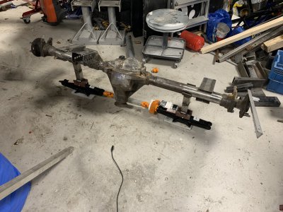
However once in the car, in their proper setting, it should work just fine.
I need to raise the bottom up a bit because even at max they're not quite tall enough.
Think I'm gonna attach a bar that goes across both of them so they can't rotate like they've done in the photo but at least it works and lifts the axle like it's nothing.
Time to quickly fix that bar and then start making the upper link mount!
This was the initial idea, where both "handle ends" would be aimed towards each other and driven from the same motor.
The U-joints take up the angular error and the shaft-in-shaft takes up any length error.
What this effectively does is reverse the direction on one jack, so when I try to raise it, one goes down and the other goes up.

So decided to bite the bullet and disassemble the whole thing and extend the lifting screw so I can rotate it from the right side.
Drilled and reamed 7mm hole in the screw and made the end of this 12mm shaft into a pressfit.
Assembled it without the extension and then pressed it in once the screw was past the nut.

Initial test just to make sure, before shortening the extension, notice the "handle part" is now on the right, outside of the image.
Works as it should now and after I milled a flat on the extension it was perfect.

I've done my best to keep this whole thing as low as possible, so I can use it as a universal lifting thing in the future.
This however means it's vastly too low to lift the axle into place, so whipped these extensions together.
I drilled a hole through the red part and the top of the jack so it's possible to secure them.

Time for an initial test.
With the small foot of the jacks, and discovering they have VERY little sideways stability(the jacks bend quite easily), it really requires whatever you're lifting to be stable on it's own.
So if I were to raise them like this, everything is going to fall and slam into the floor.

However once in the car, in their proper setting, it should work just fine.
I need to raise the bottom up a bit because even at max they're not quite tall enough.
Think I'm gonna attach a bar that goes across both of them so they can't rotate like they've done in the photo but at least it works and lifts the axle like it's nothing.
Time to quickly fix that bar and then start making the upper link mount!

- Joined
- Nov 7, 2019
- Messages
- 433
Finally making actual parts.
Similar construction as the other mounts.
Starting with 2x 40x80mm tubes, remove two walls and weld the remainders together to make a ~80x80mm tube.
I did however change my order of operations and tools this time.
Previously I have done both profiling and the holes before I cut and welded the 40x80mm tubes, pretty slow process in the CNC and always hard to align the drilled holes afterwards so the two sides end up perfectly parallel.
This time I squared one end of both tubes, removed two sides per 40x80mm tube to make two mirrored L shaped pieces.
I then clamped these together at the correct distance with random scrap and then welded the back of it to make a U channel.
After grinding the weld down I milled the open end down flat and to the correct height.
This let me do accurate scribemarks from that edge on both sides, which I then manually punched and drilled on the drill press.
Not only was this process faster but I think the holes aligned better since there was no extra distorsion after the machining proccesses.
Big downside is the large amount of grinding dust from profiling etc with angle grinder instead of milling it off.
I guess it's just one of those cases where you can't have it all, speed, accuracy and cleanliness.
A bit undecided on the sideways location of the top link.
I'm real tempted to move it further out to make bracing it easier agaisnt the rest of the 80x40 frame.
Will most likely carefully cut an oversize hole in the backseat wall so I can experiment with different placement, then weld whatever piece I need back into the wall.

- Joined
- Nov 7, 2019
- Messages
- 433
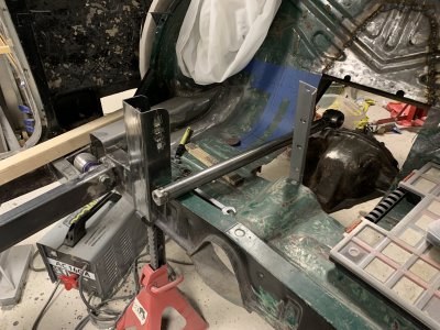
I guess it's finally a 3-link suspension and not just 2 links. 
Ended up winging it and just cutting where I had marked out, I think it will work out well once everything is reinforced.
It's all very rough work, I'll make it neat and pretty once I'm sure this is the way I want to go.
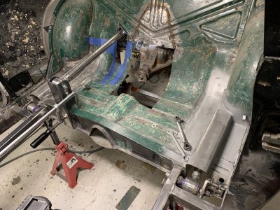
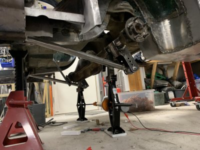
The scissor jacks has been extremely helpful finding tightspots etc.
This is as far up the axle could go without hitting the top of the "tunnel".
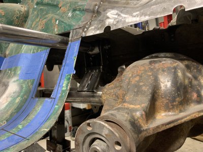
Lack of judgement made me make a much bigger hole in the rear than necessary, but no real harm done because I can close this up again in a prettier way than it otherwise would've been.
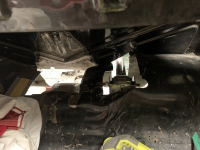
Next conundrum is that I've done something wrong, somewhere.
This is pretty much rideheight and the upper bar is parallel to the floor(to abide by the car building rules to make it street legal).
For some reason, the lower bars are not parallel to the floor.. So either I need to raise the mount on the axle(cut it shorter and reweld) or move the chassis mount further down.
I don't want to do either of them, need to contemplate this further before I take action.
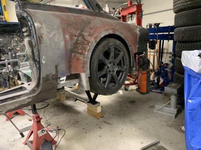

Ended up winging it and just cutting where I had marked out, I think it will work out well once everything is reinforced.
It's all very rough work, I'll make it neat and pretty once I'm sure this is the way I want to go.

The scissor jacks has been extremely helpful finding tightspots etc.
This is as far up the axle could go without hitting the top of the "tunnel".

Lack of judgement made me make a much bigger hole in the rear than necessary, but no real harm done because I can close this up again in a prettier way than it otherwise would've been.

Next conundrum is that I've done something wrong, somewhere.
This is pretty much rideheight and the upper bar is parallel to the floor(to abide by the car building rules to make it street legal).
For some reason, the lower bars are not parallel to the floor.. So either I need to raise the mount on the axle(cut it shorter and reweld) or move the chassis mount further down.
I don't want to do either of them, need to contemplate this further before I take action.


