Warco Wm14 Thread

Hello Steven, I to have started the process of converting my Warco WM14 to CNC. My only area of indecision is the X axis. Have you completed your CNC conversion and if so what size ball screw did you fit and how did you attach it to the saddle?

Again many thanks in anticipation for any guidance.
 
Hi Kaveman,
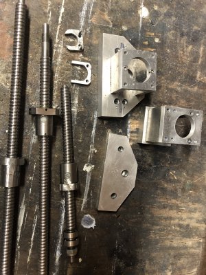
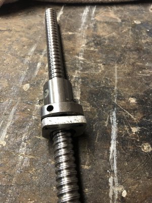
I bought the ball screw/nut from here (excellent quality):
https://www.cnc4you.co.uk/Ballscrew...llnut-RM1605-C7-16mm?search=ballscrew 1605-c7

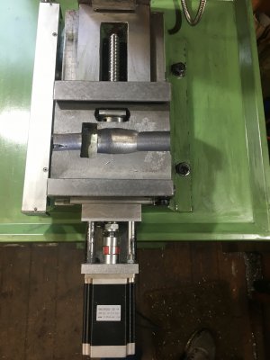
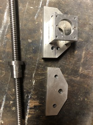
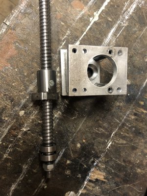
My first attachment shows the (considerable) metal removal I had to make to the top of the saddle to fit the X screw and nut. The nut itself also required considerable size reduction.

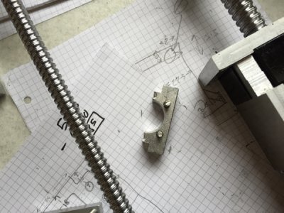
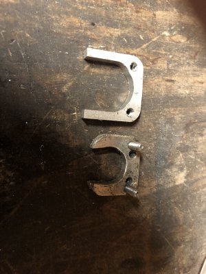
To attach the ball nut I made a fixing plate in a similar manner to AdyNI (above - I have copied AdyNI photo) except that where as AdyNI's saddle sit on top the the ball nut flange my fixing plate fitted flush on the end. I will see if I can find a photo. In the first picture you can see the flat top edge of the fixing plate for the Y-Axis poking out.

The metal easily ground down with a hand held drill and an everyday ball shaped grinding bit.

I completed the construction to the point of getting the X and Y working. But it took a great deal of going back and forth.
So - yes a 16mm will fit but it is mm tight on the underside of the table.

14mm - if the parts are available would be a much more comfortable fit. But I do wonder if 14mm will be strong enough for the Z axis? Maybe a shorter screw pitch would be better? Or use 14 for X and Y and 16 for Z.

I used an arduino with CNC shield and Chilipeppr (browser based) controller.
It worked well but (due to the low power drivers on the CNC shield) jerked a lot under load. Thus I concluded that the X, Y conversation was mechanically sound, but my electrical setup was not powerful enough and would have to upgrade to more power solution - and thus more money.

I started working on the Z axis but came to a stop because I ideally required the milling machine to be able to make the parts - thus I had to dis-assemble and re-assemble a couple of times. I did not continue but would say that the Z axis was likely to be the easiest part as it did not require any adaptation to the machine itself - just construction of some new parts.

Bottom line is, Yes it can be done especially if you have a second milling machine, but you do need to remove quite a lot of metal off the saddle for the X-axis - and a lot of patience.

What next? - I decided that if I am going to invest the money in the more powerful electrical driver setup (probably £500+) I would rather buy the WM-16 to make it worth while (not an easy financial jump I admit) - for several reasons: A heavier more stable machine for the quick direction changes that a CNC makes; I would have a second mill to make the parts (keep the WM-14 and sell it afterwards); 16mm would fit with limited adaptation; There is already a lot of WM-16 conversion information on the Web - the WM-16 is almost the same as: BF30 = G0704 = AMA25 = PM-25 (don't quote me on this).

I'll see if I can whip up some more photos.
 

Attachments

  • IMG_0374.jpg
    IMG_0374.jpg
    2.1 MB · Views: 31
  • fc4c9c405bad5cb29ea0199ab320f639.jpg
    fc4c9c405bad5cb29ea0199ab320f639.jpg
    296 KB · Views: 23
Hello Steven, thank you for such a prompt reply. I too regret that I never bought a WM16 in the first place as there is a wealth of information available to convert them, but I have had my WM14 for about 6 years and it was never purchased to convert to CNC at a later date. Now that I want to carry out the conversion I bit the bullet and bought a Sieg SX2P (I have a wonderful and very understanding wife!) in order to carry out all the remedial modifications to the WM14. Originally I was going to go with a very good and well chronicled conversion on Openbuilds that Rob Taylor carried out on a Grizzly G0758, which is the same as a WM14, however I didn't just want to copy the hard work of someone else.

So starting with the Y axis I had a rethink and instead machined out the base and saddle for the Y axis which negates the need to modify the 16mm ball screw nut as seen below.

Base original is seen first, then machined. I opened the base to a width of 50mm and to a depth of 44mm, then below that is the before and after of the underside of the saddle upon which an area of 36mm x 20mm was machined to a depth of 3.5mm to accommodate the 16mm ball screw nut.

IMG_20200303_163002.jpg
IMG_20200308_112139.jpgIMG_20200308_161623.jpgIMG_20200309_154538.jpg

Will complete all the mechanical manufacturing of the Y axis before I begin work on the X axis.

More pictures and dimensions of your conversion would be appreciated along with any dimensional information

Many thanks

Martin
 
You have managed to do a cleaner job than I managed as you had mill to work with - very nice. I'll send you over some pictures later. If you are interested you may want to buy some of the parts (very cheap, as I won't using them) - Ball screws in particular.
 
I look forward to your pictures Steven. I already have 1605 ball screws and nuts for the Y & Z axis. It is the X axis to which I am still giving a lot of thought to. As previously mentioned Rob Taylor (Openbuilds thread) used a 1204 ball screw and nut for the X axis, but I'm not sure if this is substantial as its smaller than the original so I will look into the feasibility of a 1405 ball screw and nut.

Further down the line I plan to fit NEMA 23 4.5Nm drives to the X & Y and a NEMA 34 8Nm to the Z axis. Though I have lots to do before I get to that stage.
 
The first picture if of the two fixing plates that I made to secure the ball nuts. Other pictures are: full X and Y assembly; X assembly; Y assembly; Fixing plate positioned on ball nut (but not secured - it's just sitting there).
You have probably thought of it, but if you go for a smaller diameter screw you could probably compensate by using a shorter pitch? But I have to 16mm remains ideal.
Best of luck - do keep us informed of progress.
 

Attachments

  • IMG_0514.jpeg
    IMG_0514.jpeg
    1.8 MB · Views: 14
  • IMG_0508.jpeg
    IMG_0508.jpeg
    2.5 MB · Views: 17
  • IMG_0509.jpeg
    IMG_0509.jpeg
    2.2 MB · Views: 14
  • IMG_0510.jpeg
    IMG_0510.jpeg
    2.5 MB · Views: 15
  • IMG_0515.jpeg
    IMG_0515.jpeg
    2.3 MB · Views: 18
Had a lot of time to spare in self isolation due the horrendous situation we are all having to live with, so I’ve pressed on whenever possible with my WM14 CNC conversion.

Good news is that I have now completed the Y Axis and prepared the saddle for the X Axis. After lots sketching and measuring, I have decided on a 1204 ball screw for the X Axis. I felt that anything larger would, in my opinion, involve removing too much material from the saddle. If when in use the 1204 isn’t up to it then I would go for a 1405 but that would involve a deeper recess in the saddle and some machining to the underside of the X Axis bed to accommodate the 26mm diameter 1405 ball screw nut.

As you can see from the first picture the project is progressing. I used a depth micrometer to level the ball screw when securing the nut adaptor to the original nut mounting on the saddle. Using a cordless drill, it worked nice and smooth, however it did hit a snag whereby I didn’t get full outwards movement. Upon closer examination the gib was just fouling the new front mounting bracket! Not to worry I marked the area quickly whipped off the bracket and machined a 1mm deep groove with a 4mm bull nose end mill, problem solved. Only one side needed doing but I did the other side for symmetry.

I have also included pictures of the X Axis modified 1204 ball screw nut mounted in the saddle. I can now start on the X axis brackets.IMG_20200403_130349.jpgIMG_20200403_130910.jpgIMG_20200403_140549.jpgIMG_20200402_165557.jpg
 
Just a quick update with pictures to show my current progress. It works and moves with great accuracy. I will follow this up with more detail on the conversion in the near future.

IMG_20200512_125735.jpgIMG_20200512_143716.jpgIMG_20200512_144526.jpgIMG_20200512_162603.jpgIMG_20200513_123718.jpgIMG_20200527_182751.jpgIMG_20200527_182801.jpgIMG_20200701_105506.jpgIMG_20200701_105529.jpgIMG_20200701_105544.jpg
 
Just a quick update with pictures to show my current progress. It works and moves with great accuracy. I will follow this up with more detail on the conversion in the near future.

View attachment 329366View attachment 329367View attachment 329368View attachment 329369View attachment 329370View attachment 329371View attachment 329372View attachment 329373View attachment 329374View attachment 329375
Looks great. That's about where I got to (with the use of a second mill). All move well but my drivers were not powerful enough for full scale operation - and I wasn't convince I wanted to invest the money in a more powerful controller system. Now I see what you have achieved I might just revisit. Do keep us updated
 
Hello Steven

I was extremely fortunate in having a friend who is an expert in the field of industrial automated machinery. It was through his advice that I purchased Centroid Acorn for the control system and I’m glad I did as its used by industry so there is a wealth of support both on their own website and forum and on YouTube. The Centroid Acorn board does come with free software, but it does have limitations, so I paid extra for the Acorn Mill Pro which accommodates future expansion. Here’s the link

https://www.centroidcnc.com/centroid_diy/acorn_cnc_controller.html

To be honest I don’t think I would have made such progress without his help as he modified the circuit diagrams to suit my drivers and provided sound written instructions to follow for the control box build. Then once lock down restrictions were lifted, he popped down and got the motors turning correctly.

As for the hardware I bought closed loop motors and drivers from cnc4you, 4Nm NEMA 23’s for the X & Y and a 8Nm NEMA 34 for the Z and a 600W 48V PSU. I’m currently in the process of installing limit switches then building an enclosure for which I’ve gone with 10mm twin wall polycarbonate. Will continue with updates
 
Back
Top