Ways to make a crank shaft

Almega

Active User
Registered
Joined
Feb 17, 2013
Messages
66
I am intersted in building a steam engine and I know there must be different ways to make the crank. I want to understand the various methods and the pros and cons of each. I am looking at something in about 2" to 2-1/2" stroke and would like to see ideas for both single and double throw versions. Any ideas or reference material would be welcome and appreciated.
 
Thanks for the link. That should help me move in the right direction. My crank will have a larger throw than his had, so I would think I should secure the parts into the .001 press fit holes a little better. Agree, disagree?
 
I agree, that will work fine for what you seek. Good luck in what-ever you do. ------ "Billy G"
 
I hope you follow me on the 1830 build. The crankshaft is 9 pieces. ------ "Billy G"
 
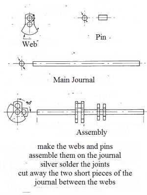
Here is one way to do it. Pretty simple and easy. Makes a neat looking crank IMO.

2-19-2013 4-57-09 PM.jpg

2-19-2013 4-57-09 PM.jpg
 
That crank could be easily cut in one piece. It would require e sets of center house at each end od the piece. One set on center, one set offset from it and another set on the same diameter only 90 degrees from the last set. This method is used a lot on 180 degree opposed cylinder engine. It makes for a very strong crank. ------ "Billy G"
 
Is there any way to calculate the size of the counterbalance on the web? I have drawn one up and it looks pretty, but I don't know if it is dynamically correct. I realize a lot depends on the RPMs that the crank will be turning; slow - no big deal - fast - BIG deal. I have looked at some large steam engines at the Henry Ford museum and those don't have any counterbalance, but turn very slowly and have giant flywheels.
 
I don't know of any off hand but I am sure there is one. On the engines the size we make counterbalance is not as big a deal. That is why you see some with no counterbalance at all. It is simply not needed and would only complicate things. I will research this for you later today. ------ "Billy G"
 
Is there any way to calculate the size of the counterbalance on the web? I have drawn one up and it looks pretty, but I don't know if it is dynamically correct. I realize a lot depends on the RPMs that the crank will be turning; slow - no big deal - fast - BIG deal. I have looked at some large steam engines at the Henry Ford museum and those don't have any counterbalance, but turn very slowly and have giant flywheels.

Here is the formula that came with a set of plans that I bought. RPMs do not appear in the calcs but certainly an imbalance will be a lot more exaggerated the faster you go ..

Equation for minimizing engine vibration:

W1 = [K*(W2+W3)*r] /X

where:

W1 = weight of the counterweight (lbs.)
W2 = weight of the crank webs outside of the main shaft and crank pin (lbs.)
W3 = weight of reciprocating parts (piston, piston rod, crosshead, one half the weight of theconnecting rod) (lbs.)

X = distance of center of mass of counterweight from center of the crankshaft (inches)

K = constant (use 0.67 for minimum vibration at right angles to the engine centerline, use 0.75for minimum vibration at crank dead center)

r = distance from center of crankshaft to center of crank pin (inches)

Generally, vertical engines should tend toward using the 0.67 value for "k", andhorizontal engines should tend towards using the 0.75 value for "k".

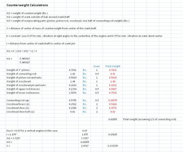
Here is an example:

COUNTERW.JPG

I have not used it, so I don't claim to understand it completely, but it seems to be what you are asking for.
I hope this is of value to you!

Dave

COUNTERW.JPG
 
Back
Top