Who is REALLY smart here, and can work this out for me pretty please... beg, grovel, beg!

Ian Bee

Active User
Registered
Joined
May 26, 2013
Messages
90
Can someone help me out here?

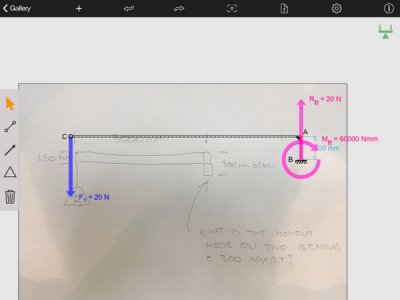
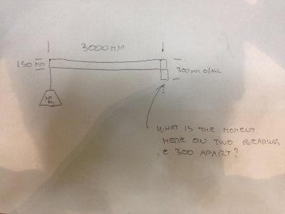
I am in the process of fabricating a boom arm for the shop, which will swivel abound its own ball bearing race.

It will be three metres long, and at the worst case, will be called upon to support a maximum load of twenty kilograms at the outer end of the arm.

My question is, is what is the lateral load on the arm joint, so I can buy the correct load rated bearings, which will be around 60.0 mm. in diameter?

The rotating part will be around 300 mm high.

As follows...

photo-2.JPG

Cheers

Ian

photo-2.JPG
 
seat of the pants tells me it's a 200kg load.

Okay, that's a good start. I have absolutely no idea how to work this stuff out. I'm sure it's got something to do with trig, sines, cosines, tangents, and other secret society stuff, which bewilders me!

It would be really neat, if someone could eventually give me the answer, as well as how they arrived at it, in a non technical term for us laymen...

Cheers

Ian
 
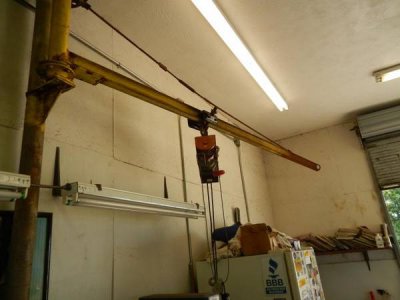
I'm pleased you got response from some smart fellows 'cause I ain't one of 'em. I can tell you how this one in my shop is made though.

The pivot is a front spindle off of a dump truck:

DSCN0393_zps25b504c5.jpg

The boom is a piece of I beam about 12 feet long:

DSCN0394_zps8c019221.jpg

I have no idea what the moment is but I can tell you I routinely lift 800+ LBS H-D Dressers off of wreckers and trailers and it doesn't flex. The 1/2" rod w/turnbuckle will get just a little taunt if I have to trolley the winch all the way to the end but that's happened twice I think with no issues. I'm able to do the lift, have the vehicle pull out from under it and then swing it over to the waiting lift and set it down gently. I'm sure over the years it's save many sore backs and more than likely prevented a few injuries.

Hope this helps.
 
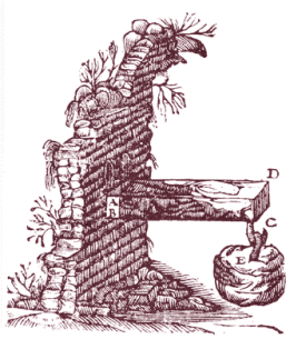
This problem was studied by Galileo in XVII century :biggrin:

MensolaOrig_Galileo.gif

I suppose you want to turn your boom (or the ball bearing would be useless!), so the force on the beam can't just be considered vertical, but there is to keep in the account the inertia of the weight, which will twist the boom.
Since my specialty was building engineering (and just with reinforced concrete) this dynamic calculation goes beyond my knowledge, but for a mechanical engineer is everyday stuff.

MensolaOrig_Galileo.gif
 
Due to liability concerns, you might have a hard time getting anyone to give you a concrete answer (sorry, no pun intended) on that one. Anytime you get into lifting devices, and suspended loads, the liability stuff gets dicey at best. But, if someone does respond and gives you some real world numbers to work with, keep in mind that you are on your own if you design and build your crane based on the technical engineering data given to you here. I don't want to sound like so many of those corporate lawyers that we have these days (no offense, Nelson) but what it boils down to is this: If someone gives you some engineering data on this forum, it is your own choice whether to proceed using that data or not, and in the event of a catastrophic failure and injuries, you cannot come back on the forum or those that gave you the engineering data and blame them. There are so many other things that can come in to play when building such a device such as welds, material quality and strength, etc. that you cannot blame failure on the data.

Okay, so now I can take off my moderator hat and give you some advice based on the jib cranes that I installed in some industrial settings. In our case, we purchased pre-engineered, commercially available jib cranes, which already have a safety factor built in, but just to be sure, we typically purchased a crane rated for 1 1/2 times the heaviest loads we anticipated. The mounting and installation was set up by an engineer, based again on the extra 1 1/2 times safety factor, and we simply followed his instructions. More than one of the engineers we consulted with commented that 1 1/2 times was more overkill than needed, but the owner of the company simply responded with "Any machine can fail, no matter how stout the design. An additional 1 1/2 times safety factor is cheap compared to what it would do to an employee and his/her family if that lifting machinery failed. I am simply taking extra precautions to make sure that I never have to apologize to an employee or his/her family because we installed something that failed and caused death or injury." He was looking out for his pocketbook too, but that is beside the point. He had a genuine interest in seeing to it that people did not get hurt at work, and he displayed that in other areas as well.

Not being an engineer myself, I cannot help you with the math on your project, but I do wish you the best of luck!
 
Okay, that's a good start. I have absolutely no idea how to work this stuff out. I'm sure it's got something to do with trig, sines, cosines, tangents, and other secret society stuff, which bewilders me!

It would be really neat, if someone could eventually give me the answer, as well as how they arrived at it, in a non technical term for us laymen...

Cheers

Ian

No trig needed. It's a lever. You've got 3m on the long side of the fulcrum and .3m on the short side so the force on the short side is multiplied by 10. 20 Kg-> 196N so the bearing static load is 1960N. I think you'll be hard put to find a 60mm bearing that can't handle five times that.

Give some thought to what the bearings (especially the upper one) are anchored to and how. Your most likely failure mode is pulling the fasteners out at the top.
 
A few things here...

1) General observation: 20 kg is almost trivial compared to the weight of the beam arm. For the US-System folks, 20kg is about 45 lbs (1/3 the weight of a typical person). Question: What is the beam material you intend to use? The weight of the beam factors heavily in this design. Question: How will you attach the arm beam to the rotating collar that holds the bearings? This is where a piece of the problem lies. Bolts can shear and welds can crack.

2) You're not really interested in the moment about the bearing. Yes, Torque = Force x Moment but, what you really want are the lateral forces applied to the top and bottom bearing. This problem is by definition a "leverage" problem not a torque problem. In this problem, the primary force will be generated by the sum of the mass of the arm beam and the maximum intended load -both considered as "point-loads" at the end of the arm beam. The leverage ratios are between the distance of the two bearings vs the length of the arm beam.

3) What is the vertical supporting column made of and what is it's diameter? This is where we to calculate torque. We need to make sure it doesn't bend -just the same we must make sure the bolts or welds don't snap.

Once we calculate the "theoretical" forces involved, we can then add some safety margins and then move on to determining what your weld or bolt strengths must be.

Ray
 
I didn't see anyone mention it but there is another consideration when figuring the total load capacity of the system and that is the "dynamic" load. All the calculations I saw referenced were for the static load on the arm (RayC at least mad mention that the mass of the arm was significant as well). When the load starts moving, or "bouncing" as it may be, the mass, as seen by the pivot point, can increase a great deal. The mass accelerates at a rate of 9.8 m/s² due to gravity.

Say that the load/winch got hung up or slipped even 10cm. Using the simple F=ma (force = mass x acceleration) and figuring the acceleration of the mass in a 10cm drop - F = 20kg x 9.8/1.01² (I calculated the time as just over a second) the Force = 20kg x 9.6 = 192n (so the equivalent of a 192kg load for this discussion's purpose). The you have to figure out the torque force at the pivot point and the added force of the arm moving, etc. etc. I'll spare you that much as you see where I'm going with this.:biggrin:

I'm not a mech. engineer (electronics engineer, minor in physics a looong time ago) so I am not sure what standards are used to rate lifting devices. I am sure they are available somewhere and hopefully someone can provide them.

-Ron
 
Back
Top