Whos got a PM-727m that can help me on a wiring snafu?

GunsOfNavarone

Registered
Registered
Joined
Jun 26, 2018
Messages
1,733
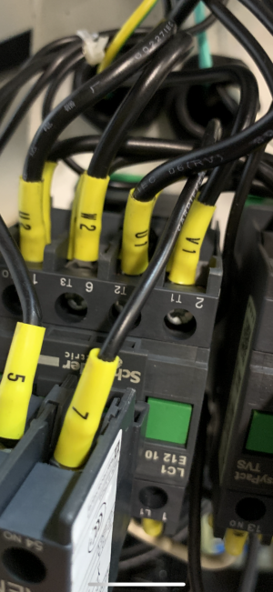
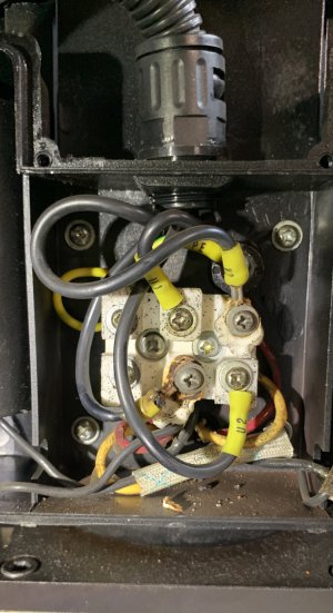
This is crazy, I've never thought about it, but let the Precision Matthews manual, "left" would be clockwise/normal cutting looking down from top of motor. Since I've had this mill, "right" is clockwise. I've never had to use the opposite direction. Anyway, when I hit the " left" rotation button, it pops my breaker. Pulling off the cover....well, bad news. After tearing it apart HOPING THIS TIME, P.M. can supply me with parts...I am replicating the wiring loom. What's odd (to me) is the leads coming into the motor wiring box, using a multimeter, the wire marked "U1" on one end is marked "U2" at contactor KM1. The wire marked "U2" at the motor is marked "U1" at the contactor.
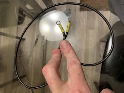
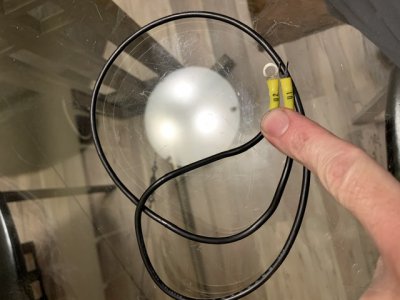
now that could be right or perhaps where they are connected could be corrected, I'm guessing with the issues, they are not. I've had a few emails with PM and it's not going smoothly. I really need to know so those 2 wire have different codes on each end and where they connect on the ceramic terminal block. I'll put some pictures of what I have, but this is a dilly of a mess.
 
So the wires in question are the front row closest on contactor KM1. This is crazy as these are the factory terminal ends...no doubt, the U1 and U2 are not the same where they terminate on opposite ends. I'm trying to believe this is supposed to be this way (?) But left face it, that nothing but confusing.
 

Attachments

  • 2020-01-04_15-18-34_000.png
    2020-01-04_15-18-34_000.png
    2.6 MB · Views: 115
  • 2020-01-03_17-13-32_000.jpg
    2020-01-03_17-13-32_000.jpg
    359.2 KB · Views: 111
i don't have a PM 727, but this may help

if the wires identification numbers are reversed, straighten out that mess before you proceed.

your operational diagram should look something like this
1578181250683.png
 
Thanks Doc. I need to FIND a new ceramic terminal block before I move on anyway. The wires on the start capacitor have about dissolved within the insulation...probably need that as well unless I can patch in some new lines there. Waiting to see if Precision Matthews can actually supply parts for this mill....I'm blown away that factory wiring snafu has made it not only to end user (2 of them) but 5 or so years out. I just want to know if this is what it appears to be. I'm guessing you're saying there is no way that is the way it was supposed to be?
 
i can't imagine the reasoning for intentionally or accidentally mis-identifying wiring- no good comes from that.
i have seen wire color changes, i have seen wire numbers change, but reversing the wire numbers between 2 conductors is not a normal practice-
at least not on anything i ever worked on.

if you have trouble finding a block, i have a few.

i'd be willing to send one, at no charge to you. :grin:

my email is ulmadoc@gmail.com,
send and address if you have trouble getting a terminal block, we'll get ya fixed up
 
I appreciate that Doc..lets see if PM comes through on this. I have really had zero luck getting parts from them, they recommend going online. Being I've done that (for hours) & can't find one SIMILAR enough, I'll be in needy place.
Does your block have the ability to connect wires from front & rear, or at least side and front? I'll happily PayPal you $ for shipping etc...
 
The wires to the contactor are the same as the connections shown in the manual. It appears confusing most likely because it is a single phase reversing motor and the thew two contactors need to switch multiple connections. It looks like the motor terminals became loose and this caused some arching and heat buildup as well as the ceramic looks broken possibly from heat or over torqued screws. If the motor leads were longer you could possible extend them and make connections to a new terminal block or to an external electrical box to make the proper connections. I am a bit concerned because the insulation looks burned. The ceramic motor terminal is integral to the motor, doubtful it would be a replaceable part. Have you looked into a new motor?

Left is the manual KM1 right is yours, they seem to be wired the same.
pm-727.jpg
 
Thanks MKSJ. I know this is confusing, but the wire listed as U1 in that picture, has a U2 on the other end. The one that says U2 says U1 at its other end. Hard to phathom, I know. That terminal block will be replaced, I'm not seeing any resistance on any of the motors leads, so I don't believe the motor is bad. That terminal block isn't part of my motor, just a junction block to connect wires together.
I was originally asking if anyone else's U1 and U2 leads had the wrong terminal codes on terminating ends...but that would be pretty odd.
 
Ok, so here are the factory wires, untouched, printing on terminals still there and they are on tight, look to have never been recrimpt. This is my concern before I put it back together. Is this a huge factory screw up, or do I replicate this? Anyone that has this machine, and you want to waste 5 mins, I’ll let you know where to check this as a huge favor to me.
 

Attachments

  • A30A3754-58AE-4A7A-B10E-89BF0A243FD3.jpeg
    A30A3754-58AE-4A7A-B10E-89BF0A243FD3.jpeg
    77 KB · Views: 114
  • D930A1F2-A05E-4AB8-8A3E-5F76234470F5.jpeg
    D930A1F2-A05E-4AB8-8A3E-5F76234470F5.jpeg
    78.6 KB · Views: 108
My experience with the schematics is they often do not match the actual wiring, just show the connections. Showing a wire with two different labels would not be unusual for a single phase motor, but it is hard to say just showing a wire and not what it was connected to. Since L and N connections to U2 and U1 are flipped along with the respective connections to each contactor, then the numbering and lettering could be different at each end. So the blue N line I would expect to have a U1 on one end and a U2 on the other end and these would be connected to the N at one of the terminals. The red wire connections would most likely be labeled differently depending on which terminal it is connecting to. I try to map out the wiring that I see to the schematic, but it is often difficult to follow. As long as the proper motor connections are connected and the motor was running correctly before, then I assume it was wired correctly. The other problem I have seen with Asian main power wiring is the power leads, neutral is typically blue, brown is the power leg, yellow/green is ground.

As far as the motor terminal on these types of motors, the ones I have seen are attached to the motor and not a separate terminal strip. In motors with leads and a larger electrical box I have attached the wires to a separate terminal block that had a plastic top to prevent shorting.
727 schematic.jpg
 
Back
Top