Why is 220V called single phase when it has two phases?

Thanks! I think:thinking:! :whistle: LoL! As the eyes roll back into my head! Glad I could generate a topic of such great discussion! I got the basics of my question answered. On to the next item to ponder ......... whatever that may be!
 
Our local power company stopped providing 240V 3 phase and went to all 208 or much higher. There are no "wild legs" (as there are on 240V systems) on a 208V 3 phase so you can use any leg to neutral as a 120V "house hold power." It helps the power company balance out the leg to leg power flow. Our shop has lots of European equipment. It runs fine on 60 cycle just 20% faster than "as designed" (50 cycle.) That makes quite a difference on the motors running on frequency converters (14,400rpm VS 12,000!). We have lots of 3 phase 380/400V transformers for those machines.
 
Simple the AC motor can not on just single phase. So second winding at 90 deg or 2 phase. A capacitor is use to form the two phase from the single phase


There is shaded pole AC motor but only use on very small motors
Something that I've been thinking about for a while. Why is 220V called single phase when it has two opposing phases? As I understand it, 3 phase has 3 60 hz 120 degrees opposed.

Sent from my SAMSUNG-SM-J320A using Tapatalk
 
What I said up there is rubbish. No idea where my brain was.......out to lunch I suppose. Center tapping does NOT split a phase. Current flows between the windings in a turn:turn ratio and that is used to reduce, increase or at times make no change to the voltage. That's about it. Center tapping simply allows one winding to act as two, or even can be multitapped at different points yielding different ratios and therefore voltages.

I apologize for the brain-dead misinformation.
 
OMG: Deja Vu... This is a really old thread. -So let's not waste this opportunity to dredge it up..

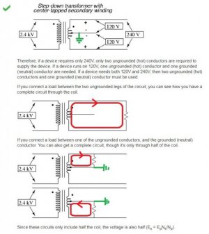
Please see the image below which was captured from this link: https://diy.stackexchange.com/questions/33602/why-do-240v-circuits-not-require-neutral


I have modified the original image to make it easier to understand. In the diagrams, a ground connection was added to the center-tap. In reality, this is what happens. I have also added + and - symbols in the top diagram. The ground leg by definition is considered to be the - (negative) leg. In the top diagram, if you were to put a bridge rectifier at the end of each 120 volt leg and measure the voltage with a DC volt meter without flipping the leads, one leg would read positive, the other would read negative. This is where the perceived phase shift comes into play ... because the voltage is reversed. If you were to draw this out using phasor diagrams, the representation is called a phase shift.


220CenterTap.JPG

Ray
 
The answer is buried in your original post in that the two legs of a 240-volt system are offset 180 degrees. The 240 is derived by averaging potential difference measurements taken from intervals across the positive waveform and that exact same point on the corresponding negative waveform - which is why you are getting 240 volts - that is the difference between the mountain and the gorge. In three phase the waveforms are staggered 120 degrees as you say and because there is less "dead" space between cycles, averaging waveform measurements result in a line-to-line voltage (phase to phase) voltage that is 1.73 x phase to neutral voltage.
 
It is a logical extrapolation from 3-phase to think that single phase 240V with neutral might be thought of as 2 phase. I have asked this same question myself (I am an electrical engineer working in the microwave antenna field). None of the explanations I was given were convincing to me. I think the real answer is that historically the electric power industry just decided to call it single phase.
 
Maybe this will help.

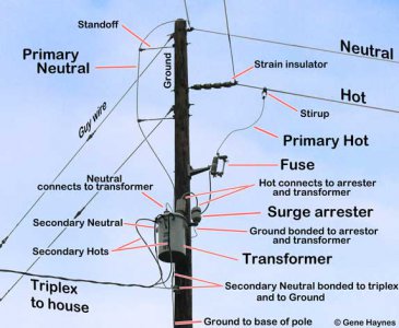
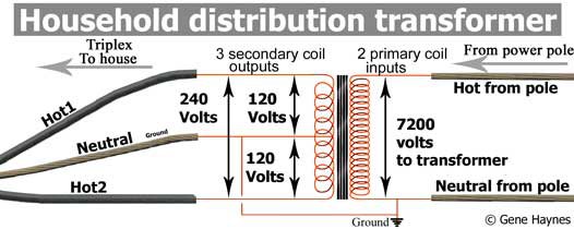
The power going to most residential service (In the US), is 1 leg of the three phase high voltage. That 1 leg, is then lowered by transformers into 2 120 volt, legs, and a neutral. If you look close at the transformer, it has 1 hot going in, and 2 half voltage hots coming out, and a ground in and out.

Here is a good page that explains it.


http://waterheatertimer.org/See-inside-main-breaker-box.html

There is such a monster as 2 phase, in some parts of Philadelphia, and a few other rural areas in the US. So you can run across 2 phase motors once in awhile.

IMG_4081-residential-service-6.jpg

Household-transformer-32a-550.jpg
 
What cleared this up in my head was looking at waveforms on an oscilloscope several years ago when I was cutting my teeth on electronics. I had seen some banter back and forth on electronics forums; someone was saying 3ph is out of phase by 120deg and single phase is out by 180 degrees, some disagreed, and I didn't know who to believe. I learn best hands-on, so I set out to resolve it myself.

Using an isolated oscilloscope (fluke scopemeter) I looked at the 3 phases of a 480V supply. Probe 1: ground to L1, clip to L2. Probe 2: ground to L2, clip to L3. Probe 3: ground to L3, clip to L1. I get 3 sine waves separated by 120 degrees, as expected.

Now I go to do the same thing on a 240V single phase supply. Probe 1: ground to L1, clip to L2. Probe 2... what do I do with probe 2?... ground to L2 and clip to L1? That's just monitoring the same thing as probe 1, but with inverted polarity. But whatever, let's try it... ground to L2 and probe to L1... aaand... It's "180 degrees out of phase" with what? ... with itself. There is only one phase, and saying it's "180 degrees out of phase" is a waste of your breath and everyone else's sanity.
 
The center tapped transformer is stupid and they should have just done 220V without the neutral, but we're stuck with it now. There was probably a good reason back in the day with insulation requirements and such. From the power companies' perspective, it's one phase of a 3 phase feed, so single phase. The center tapped neutral L1/L2 creating opposed waveforms doesn't matter to them.

Even better would be 3 phase 480V standard, but that's pushing it. :)
 
Back
Top