-
Welcome back Guest! Did you know you can mentor other members here at H-M? If not, please check out our Relaunch of Hobby Machinist Mentoring Program!
You are using an out of date browser. It may not display this or other websites correctly.
You should upgrade or use an alternative browser.
You should upgrade or use an alternative browser.
[How do I?] Wire A Motor To A Drum Switch
- Thread starter Charl
- Start date
- Joined
- Jan 18, 2016
- Messages
- 398
http://www.hobby-machinist.com/thre...tor-drum-switch-and-ground.44391/#post-379534
This is for peerless, not furnas. Might help.
I have this task coming up also. Mine drum switch is currently not reversing.
This is for peerless, not furnas. Might help.
I have this task coming up also. Mine drum switch is currently not reversing.
- Joined
- Apr 12, 2015
- Messages
- 1,463
View attachment 125560 View attachment 125561
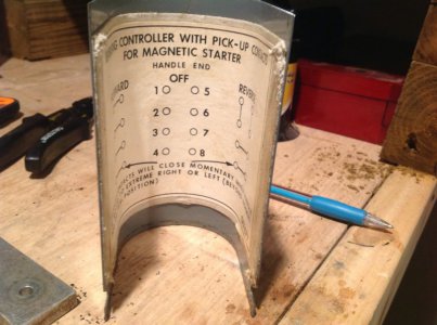
I'm trying to wire a 115v single phase motor to a furnas drum switch. It should be simple but the more I search on the net the more confusing it gets. I have 4 wires from the switch to the motor (red, white, black, green) and then power to the switch. Please help!
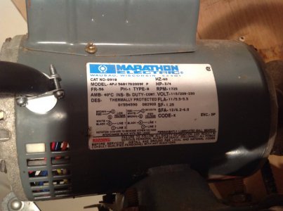
You do not state what terminals on your motor the red, white, black, and green connect to. But, if you want to wire you motor up to the drum switch based on the motor nameplate and the drum switch diagram (I cannot read the information on the 4 and 8 terminals on the diagram). This is how you want to connect the motor.
1) Terminal 2 of the motor is wired to terminal 1 of the DS.
2) Red wire from motor is wired to terminal 5 of DS
3) Black wire from motor is wired to terminal 2 of DS
4) Terminal 4 of the motor is wired to terminal 6 of DS
5) L2 source voltage is wired to terminal 3 of DS
6) Terminal 7 of DS to terminal 1 of motor
As long as you have the brown wire from motor connected to terminal 2 of motor, white wire of motor connected to terminal 4 of motor and L1 (neutral of source voltage) you will have on/off/forward/reverse of the motor when sources by 120Vac.
If you draw this out, you will see that the Black wire and Red wire are switched by the drum switches diagram when moving from Forward to Reverse.

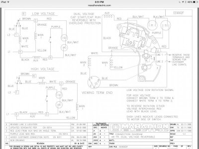
This is the motor schematic and diagram.
Red, white, black and green are not connected. They are run to connect the motor to the switch.
Terminal 2 has brown and red connected to it with no open space for any other connection. Terminal 4 has white and black connected with open space for more connections. Terminal 1 is open with no connections as is terminal 6 and 5. I appreciate the help.
- Joined
- Apr 12, 2015
- Messages
- 1,463
View attachment 125567
This is the motor schematic and diagram.
Red, white, black and green are not connected. They are run to connect the motor to the switch.
Terminal 2 has brown and red connected to it with no open space for any other connection. Terminal 4 has white and black connected with open space for more connections. Terminal 1 is open with no connections as is terminal 6 and 5. I appreciate the help.
The Red and Black wire go to your AUX winding, which is the start winding of the motor. It is this winding that determines the rotational direction (depending on it's polarity) when the motor is started. This is the winding that has to go to the Drum Switch so you are able to change the motor's direction. Note, once the motor is running, the Drum Switch has no effect on changing the direction until the motor comes to a stop (no worries of slamming the motor into reverse while running). This is due the the centrifugal switch shown in your schematic. It switches out the start winding once the motor is up to speed.
To wire in the Drum Switch, you have to insert it into the wiring of the motor, what I outlined in my last post does that. This means taking off the existing Black and Red wires from their current terminals and adding additional wiring of the proper type and size for this application.
To start, disconnect both the Red and Black leads from their respective terminals as outlined and extend those wires to your Drum Switch. Then run additional wires from the motor terminals I outlined to the Drum Switch.
If you are not comfortable with and fully understand what is needed to be done, please ask for assistance from a motor shop and/or electrical technician. You need to hook this up properly, ground the system for safety, and use the proper gauge and type of wire for your equipment.
- Joined
- Jan 18, 2016
- Messages
- 398
Thanx CraigB, Bookmarked for when i tackle mine.
Thank you! I will tackle it this weekend.The Red and Black wire go to your AUX winding, which is the start winding of the motor. It is this winding that determines the rotational direction (depending on it's polarity) when the motor is started. This is the winding that has to go to the Drum Switch so you are able to change the motor's direction. Note, once the motor is running, the Drum Switch has no effect on changing the direction until the motor comes to a stop (no worries of slamming the motor into reverse while running). This is due the the centrifugal switch shown in your schematic. It switches out the start winding once the motor is up to speed.
To wire in the Drum Switch, you have to insert it into the wiring of the motor, what I outlined in my last post does that. This means taking off the existing Black and Red wires from their current terminals and adding additional wiring of the proper type and size for this application.
To start, disconnect both the Red and Black leads from their respective terminals as outlined and extend those wires to your Drum Switch. Then run additional wires from the motor terminals I outlined to the Drum Switch.
If you are not comfortable with and fully understand what is needed to be done, please ask for assistance from a motor shop and/or electrical technician. You need to hook this up properly, ground the system for safety, and use the proper gauge and type of wire for your equipment.
- Joined
- Apr 12, 2015
- Messages
- 1,463
Great!


