Wiring a 575V 3 phase motor Help Please

mlalonde

Registered
Registered
Joined
Aug 27, 2018
Messages
24
Hi

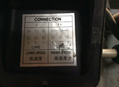
I purchased this mill/drill from a guy who didn't have 3 phase and decided he was going to repower it with 220 single phase. I have 3 phase and would love to get this thing wired for 575 3Phase again. I will attach a couple pics. In the one pic there are 7 wires. 6 black and one green. the 6 black are numbered from 1 through 6 and of course the green is ground . So what I need to know is what terminals does the wires numbered 1 through 6 go to???Motor wires.jpgmotor swicth wires.jpgmotor cover.jpgKing_401_KC-401V2F_Mill_Drill_334075_01.jpgMotor plate KC.jpgswitches.jpg
 
So what I need to know is what terminals does the wires numbered 1 through 6 go to???

That's a good question.

You have a 575V, 2 speed, 3 phase motor. And according to the diagram:
Low speed is L1-U1, L2-V1, L3-W1; U2, V2, W2 not connected, normally switch position 1
High speed is L1-U2, L2-V2, L3-W2; U1, V1, W1 connected together, normally switch position 2

I would switch to #2 position and find the 3 wires that are connected together, the other 3 will be from L1, L2, L3. Then it's just a matter of assigning L1, L2, and L3 to a wire number....... I think. :cautious:

Then switching to #1 position, assign L1, L2, and L3 to the matching wire.

Without a full wiring diagram, the wire numbers are meaningless until you assign them.

Somebody check my logic here....... Please! :confused 3:

Also check for other wiring changes, maybe a control power transformer that could be wired for 240v.
 
Jim is correct, you will need to use a continuity tester to identify the two sets of 3 wires for each of the two speeds. You should try to find someone knowledgeable in electrical things to help you if you don't have experience in this area, especially if there are relays involved inside the switch box
 
this looks like a two speed motor where connecting in star is the low speed, and in delta the high speed. From the number of wires, green is earth, and the 3 windings are U V and W. for low speed connect phases to U1 V1 and W1, and connect U2 V2 and W2 together. For High speed, connectU1 to V2 V1 to W2 and W1 to U2. However, you seem to have a remote speed change switch which performs this function. There should be 6 wires from this switch, so that you can connect each of the six wires from the motor to the switch, but they must be connected in the right way so that the switch can perform the interconnectiions for you You need to look at the wires from the switch, and see if they are labeled, or look at the switch to see if it is marked, or you need to test out with a multimeter to see which wires from the switch are connected in each of the two speed positions, and work how to connect it up, easy for a sparky, but not so easy if you are not! Can you get a local sparky to look at it? East Yorkshire is a bit far from Ontario!
 
this looks like a two speed motor where connecting in star is the low speed, and in delta the high speed. From the number of wires, green is earth, and the 3 windings are U V and W. for low speed connect phases to U1 V1 and W1, and connect U2 V2 and W2 together. For High speed, connectU1 to V2 V1 to W2 and W1 to U2.........
That's not at all how I read the connection diagram in OP's pic #3. Jim has it right in post #2.

That's a good question.

You have a 575V, 2 speed, 3 phase motor. And according to the diagram:
Low speed is L1-U1, L2-V1, L3-W1; U2, V2, W2 not connected, normally switch position 1
High speed is L1-U2, L2-V2, L3-W2; U1, V1, W1 connected together, normally switch position 2
.
.


Tom
 
Hopefully, there are some identifying marks in the motor terminal box that will show T1, T2, etc.
575VAC is very dangerous - it would be worth it to get a competent industrial electrician.
 
This motor has only 3 windings, and 6 wires, not connecting anything to W2 means that winding is doing nothing, if it had split winding for series parralell speed change it would be a 12 wire motor. in pic 3 the star connection is correct, but the delta diagram shows no connections between coils, and in delta the coils are connected together end to end in a set sequence. Jims method for finding the connections to the speed change switch is identical to mine. three phase is three phase regardless of the voltage. Wiring the motor is not the problem, that is easy, it is wiring the switch to the motor that is difficult, and probably beyond the realms of the OP to do safely
 
I agree that your switched connections are correct for 2 speeds, but what I meant to point out, rather clumsily, was that your high and low speed designations were reverse of the nameplate diagram.

Tom

this looks like a two speed motor where connecting in star is the low speed, and in delta the high speed.......

1579033928882.png
 

Attachments

  • 1579033890730.png
    1579033890730.png
    503 KB · Views: 0
I think the low speed is a delta connection, and the high speed is a double star where the windings are parallel.


1579040206492.png


1579039776152.png
 
Last edited:
I think the low speed is a delta connection, and the high speed is a double star where the windings are parallel.


View attachment 310648


View attachment 310647


That's how I'd read it too, and explains why the diagram on the plate shows one end of each coil unconnected - they're connected internally.

You're into some reverse engineering with that if it's been fiddled with to run at low voltage. That original wiring scheme is high voltage only and can only be modified to run low voltage by changing some connections internally to run parallel delta. I ran into the opposite problem on my bridgeport and made a video about modifying the motor wiring scheme. Might help you:

 
Back
Top