Wiring a forward/stop/reverse switch on an Atlas 618???

rac1812

Registered
Registered
Joined
Nov 8, 2017
Messages
41
I have the lathe running but this switch, which I think is original, is always staring me in the face.

Is there a generic diagram that shows how to wire this contraption??? Power will come to the switch first then will flow into the motor terminals dependent on how the rotor arm of the switch is pushed........ how do I identify the "other" connection tab that will reverse the rotation. I have reversed motor direction before but they were always new with instructions.... this is an oldy 1/3hp that came with the lathe.

Final question...... what is the value of the reverse rotation on a lathe??? is it really needed ........ when am I likely to use it...... or should I just install a modern kill switch like on my belt grinder???

.Caution I am a newbie with just enough knowledge to be dangerous.

Bob C
 
If you do add reverse to your lathe, be careful. The chuck is threaded on and can unscrew with the lathe in reverse. Not to say you can't do it, but do some searching and learn about the issues.
 
As Bob mentioned be careful if using reverse. I also have threaded spindle.

I have only used reverse when threading, and then in backgear so slow speed. Still need to keep an eye that the chuck does not come loose.

I do not think there are generic drawings, many drum switch designs.

The motor should have a wiring diagram which defines the two wires whose positions are switched to change the motor from Forward to Reverse.

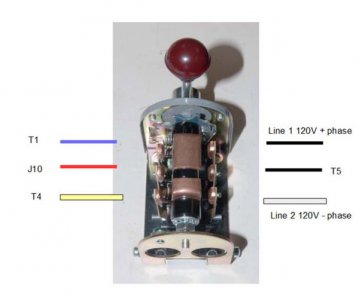
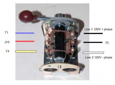
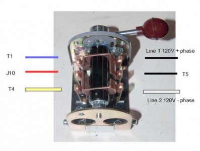
This is the diagram for my drum switch on my SB Heavy 10. I added coloured lines to show how this is wired.

OFF position.

Drum_switch_off.jpg

Forward position.
Line 1 connects T1 and J10.
Line 2 connects T4 and T5.

Drum_switch_forward.jpg

Reverse position.
Line 1 now connects T1 and T5.
Line 2 now connects T4 and J10

Drum_switch_reverse.jpg
 
I have the lathe running but this switch, which I think is original, is always staring me in the face.

Is there a generic diagram that shows how to wire this contraption??? Power will come to the switch first then will flow into the motor terminals dependent on how the rotor arm of the switch is pushed........ how do I identify the "other" connection tab that will reverse the rotation. I have reversed motor direction before but they were always new with instructions.... this is an oldy 1/3hp that came with the lathe.

Final question...... what is the value of the reverse rotation on a lathe??? is it really needed ........ when am I likely to use it...... or should I just install a modern kill switch like on my belt grinder???

.Caution I am a newbie with just enough knowledge to be dangerous.

Bob C

You need reverse to run the lathe i on the correct direction when the lathe is in back gear or to remove a tap that you just drove in under power.
 
Hi Bob there are two basic drum switch types, I call 'em chopstick and hockystick. Both can be made to work.
Can you post pictures of your switch and motor? Need to see which type of drum sw. and your motor connection nameplate info.
Mark
ps reverse is useful if you need to do metric threading since you can't use your threading dial. Many people find that they use it very seldom, if at all
 
Last edited:
When I use a 3 jaw chuck on my wood lathe.....and expect to run it in reverse for sanding, I install a thick leather washer on the threaded shaft which compresses whenthechcukis scredwed in and seem to provide enough tension to keep it in place.

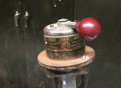
Photos of the switch this afternoon.

Bob C
 
When I use a 3 jaw chuck on my wood lathe.....and expect to run it in reverse for sanding, I install a thick leather washer on the threaded shaft which compresses whenthechcukis scredwed in and seem to provide enough tension to keep it in place.

If you install something like this on the metal lathe chuck you will create a lot of runout. Likely have runout on the wood lathe, but do not notice.

I have wood and metal lathe. I do not know any wood turners who measure runout on their wood lathes, but likely there is some.

If I remove my metal lathe chuck, I re-true this on installation. On the wood lathe I remove and reinstall the chucks and do not measure runout.

You need the metal lathe chuck register/shoulder to mate with the registration surface on the spindle.
 
You need reverse to run the lathe i on the correct direction when the lathe is in back gear or to remove a tap that you just drove in under power.

My Atlas/Craftsman 6x18 runs correctly in the forward position whether in direct drive or back gear. The back gear runs in the opposite direction but bull gear runs correctly.
 
The previous posts pretty much cover the subject with drum switches. I personally use a "DC Reversing" switch arrangement for several machines. Herein, with a single phase motor, the start winding and the run winding both come out to a terminal point somewhere. When they do not, I open up the motor and create one. To reverse that single phase motor, simply reverse the relationship between the start and run winding. This sounds complicated, but really isn't, once the wiring is understood. In one installation, I use a (fairly common) 4-way light switch. In another, I use a similar hand built switch (DPDT-CO). The important thing is to understand the motor wiring and that the motor must return to zero speed before reversing. Unlike a three phase motor, it cannot be plugged. It will take a couple of days to generate a drawing showing what to modify. An interesting idea, but time will tell.

The really important issue is to remember that when reversing a lathe (or any other machine) a threaded fastener will unthread. On mine, I pin the chuck through a drilled hole into the spindle. Not a recommendation, just a solution I use. And then only if the job will involve reversing.

The chuck backing plate is referenced to the shoulder on the spindle. The threads are there only to run the backplate onto the spindle. The shoulder is where the runout comes from. There should never be anything between the spindle and the chuck on a metal lathe. There will be runout.

Bill Hudson​
 
Well I played with it.

I took the switch apart but it only come out so far....the bakelite portion with the connection comes out but the rotor with the copper segment cannot be removed.... the PO hammered the top shaft as a rivet.

Anyways I installed a line L1 and L2 and using a tester cannot tell which of the other four screws are flowing using AC current...... any two pair of screws give me a live 120V.

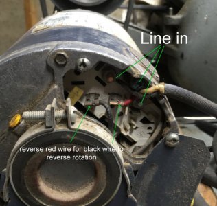
Looking at the label on the motor and the attached photo reversing i a simple matter of reversing the black wire for the red wire...done that it works....

At this point Bill's suggestion just to wire in a DPDT center off switch is probably the easiest thing to do.......

A simple wall switch in a box can be the master on off.

However, I am still intrigued to see if I can sort out with of the 4 screws inside the Furn-ass switch flows in which direction........ I may try using a 12v DC PS and my tester.

A quick search as turned up a whole bunch of Furn-ass swithces on the web which I need to consult further.

Will let you know the outcome.

Thanks for your help.

Bob C.

IMG_0914rez.jpg

IMG_0935textrez.jpg
 
Back
Top