Wiring a harbor fright single phase reversible motor w/ a vintage drum switch

makeparts

Registered
Registered
Joined
Dec 9, 2019
Messages
89
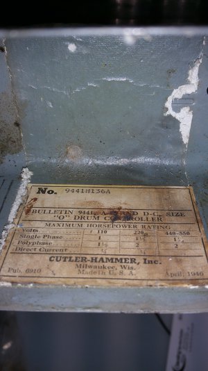
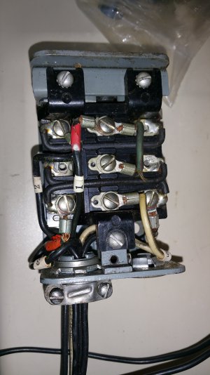
not too many threads with the chinese 4 wire motors, but after much perusing, some videos and articles, I've managed to create the below diagram to wire the motor that came with my little Craftsman 101, and a vintage rotary switch that is also 115V single phase capable.

Im pretty sure Im missing some things, but this is as far as I could get over the weekend.

some basics for the effort
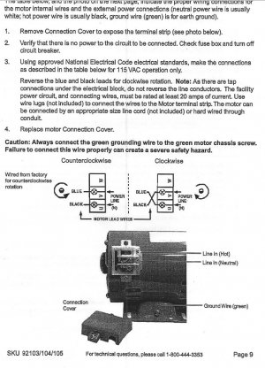
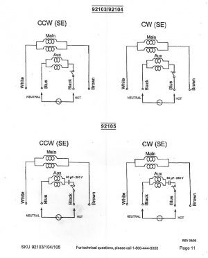
Motor is a Chicago Electric Power Tools (Harbor Freight) 92105 motor
115VAC, 60Hz, single phase 1/2hp reversible motor (CCW on facing shaft)
5amp no load, 7.54amp peak, 1725rpm
NEMA 48, 5/8" shaft
Four poles fan cooled, centrifugal switch, capacitor start
 

Attachments

  • motormanualpage9.JPG
    motormanualpage9.JPG
    148.7 KB · Views: 30
  • motormanualpage11.JPG
    motormanualpage11.JPG
    79.4 KB · Views: 31
the switch is a Cutler-Hammer 9441 series - No. 9441H136A to be exact.

it looks like it's in ok shape, and mechanically sound, but it will get a cleaning and going over, when I get the wiring diagrams figured out.

I've not ohmed the switch out, nor have I modified any of the internal connections since I got it. it was an ebay find, and the seller mentioned he had tested it. I will verify, but have not yet.
 

Attachments

  • 20200105_185301.jpg
    20200105_185301.jpg
    905 KB · Views: 19
  • 20200105_201659.jpg
    20200105_201659.jpg
    860.9 KB · Views: 17
  • 20200105_201730.jpg
    20200105_201730.jpg
    712 KB · Views: 17
  • 20200105_201845.jpg
    20200105_201845.jpg
    773.5 KB · Views: 14
That's a large CH drum switch. Size you would see on a perhaps a 1-3HP motor. Looks like the one on my mill.
Should be more that ample.
 
I am not 100% sure, but from what interwebs research I have done, the windings for the coils are already tied together internally in the motor, thus there are only 4 leads plus ground on the motor.

that said, here's what I have come up with for a connection schematic. I tried to upload the manual for the 92103/104/105 series of Harbor Freight motors, as that manual appears to have dissappeared, in case anyone needs it, but's it's too large, per board limits. PM if you want a PDF or TiF copy of it.

how does it look?
am I missing a ground connection in the switch?

Im not really a circuits guy, but am willing to do the work.
also, what gauge wiring should I use? 14gauge?

wiringdiagram.JPG
 

Attachments

  • wiringdiagram.pdf
    289.2 KB · Views: 5
That's a large CH drum switch. Size you would see on a perhaps a 1-3HP motor. Looks like the one on my mill.
Should be more that ample.
I thought it would be ok, too. picked up it for a good price (if I recall, it was maybe $50, shipping included)
 
Hmm I think your connection diagram isn't quite right. I believe that is a three-pole, double throw switch is it not?
-mark
 
Hey Mark - thanks for examining my mess of a schematic!

Im not sure, but from my very limited knowledge it looks like a triple pole switch.

I haven't sat down to ohm out the paths, and I can't find a switch schematic anywhere. Would any 9441 series drum switch schematic do? I've been looking for the specific part number.

If one looks closely, there are some "permanent" jumpers that have been soldered in. Would I need to remove those, in order to determine the base functionality of the switch?
 
You won't be able to ohm it out without disconnecting those jumpers, but with the switch cover off you should be able to physically see what connects to what and diagram it out. Drum switch internal connections are not consistent from one manufacturer to another so it's best to determine the connection pattern first.
 
That switch is different compared to the usually seen Furnas style. Just use an ohmmeter to test it- with the jumpers off of course
I think the three center terminals are the wipers
 
I had 30 minutes yesterday to take a look at the switch. I was able to pull it apart, and look at the logic, and check the physical state of the switch, and ohm it out. (please note the Fwd and Rev positions are reversed from my previous schematic, but the terminal labels are good). I’ll update that diagram when I take my next stab at the schematic.

What are the contacts of these old switches made of? A copper or tin alloy? What should I use to try and clean up the contacts?

All the wires (internal soldered jumpers, external connections) appear to be 14 gauge. Is this what I should be using, to rebuild the external wiring and jumpers, if needed? Should I be using multi conductor SOOW wire?

Also, should I try to use the existing jumpers, or clean them off and start from scratch?

I was able to observer the switch logic, and ohm it out, with the caveat that there were still jumpers on it. Knowing what to expect with the switch pulled apart, and close examination, I'm pretty sure the basic switch logic, without soldered jumpers, is as follows (contacts labelled in diagram below). Note when in the neutral position, no contacts were mated in the switch at all.

Switch Position​
Reverse​
Neutral​
Forward​
C1 <-> B1​
A1 <-> B1​
C2 <-> B2​
A2 <-> B2​
C3 <-> B3​
A3 <-> B3​


The internal soldered jumpers are as diagrammed in the image inserted:
switch internal connections.png

Keeping in mind this switch was purchased off the interwebs, and not with the lathe being rebuilt, it's unknown what it was connected to, but it was most likely a reversible motor. The external connections were labelled with numbered labels, as follows:

External wire 1 (black) connected to switch terminal B1
External wire 2 (black) connected to switch terminal A1
External wire 3 (Black) connected to switch terminal A3
External wire 4 (Black) connected to switch terminal C3
External wire 5 (White) connected to switch terminal B3

I've also attached some images of the switch internals

Wont have any time to work on updating the schematic until next weekend, but I wanted to document what I found.

switchFWDpostion.jpgswitchNEUTRALpostion.jpg
switchREVpostion.jpg
 
Back
Top