Wiring Barrel Switch Enco 110-0818

Chrisgr

Registered
Registered
Joined
Oct 21, 2020
Messages
10
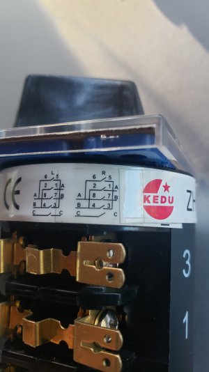
SO i just bought this old 1990 Enco Lathe...cool little lathe and it's in great shape but the switch is worn out. This is the closest switch I could find, without taking out a second mortgage and selling a pet or two but I cant figure out how to wire this thing, any one have experience with this?

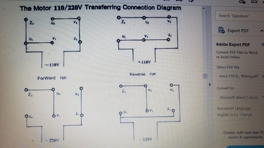
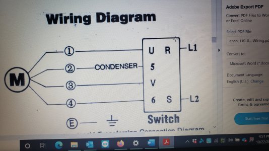
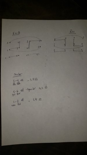
Attached is the wiring diagram for the new switch, and a factory wiring diagram for the lathe with the old switch. I am not very familiar with switch diagrams, and, coming out of the motor is a total of 6 wires plus a ground, labeled 1-6. I think two pairs of the wires are a start and run circuit, but not sure about the other two, and they do not appear to be on the factory wiring diagram. There is also a capacitor (start i think) on one of the motor circuits. Any suggestions on how to wire this thing with out burning down my new shop?
 

Attachments

  • Barrel Switch 20201022_163737.jpg
    Barrel Switch 20201022_163737.jpg
    864.6 KB · Views: 31
  • Enco Wiring 1.jpg
    Enco Wiring 1.jpg
    5.3 MB · Views: 26
  • Enco Wiring 2.jpg
    Enco Wiring 2.jpg
    4.6 MB · Views: 27
you have a 6 pole motor.
it can be run 115v or 220v with capacitance, or, on 220v 3 phase (delta or wye configuration) without capacitance.
what voltage are you looking to wire this up in?
what voltage is the motor tapped for now?
in essence, you'll be switching U2 and U1 in reference to Z2 and V1 respectively to get directional control
 
Ulma, I really appreciate the help on this. The motor is currently wired for 115V with the capacitor, and it will remain that voltage. When you say to switch U2 and U1, how do i accomplish that on this new switch? Below I mapped out the new switch using a volt meter, as well as the motor circuits and identified the start circuit. Which wire would go to which terminal on the new switch to achieve the directional control?
Thanks again.
 

Attachments

  • Barrel Switch and Motor Map.jpg
    Barrel Switch and Motor Map.jpg
    884.2 KB · Views: 38
Let me study your info for a bit, maybe help out here
Question 1: what are those curved lines on your switch diagram? Jumper wires?
Question 2: is this a 3 position switch? No terminals connected in center off position?
-Mark
PS your motor start capacitor may be shorted if you get a steady low ohms reading on wires 5 and 6, the start leg circuit. Normally you should see the meter swing low then climb towards infinite ohms. Reversing the test leads you should see this effect each time. Measuring the cap by itself should see this also.
 
Last edited:
Hi Mark....yes, 3 position switch, and curved lines are jumpers built into the switch but they can be removed. The Vertical connections between 2-4, and 6-8 are also jumpers and are permanent. I don't think any terminals are connected in the off position, but i will double check. "C" terminals show continuity in forward and reverse only.
Thanks
 
No continuity between any terminals (except jumped) when switch is in Off position
 
Can those "permanent" jumpers be removed also or are they spot welded in place or something similar? Could they be cut if necessary?
Also, what was the story with the readings of wires 5 and 6? Was that just the winding itself or with the capacitor in the circuit?
Are there two pairs of C terminals or just one pair?
-M
 
I don't think they can be removed without damaging the switch. The way i understand the OHM readings, is there are three circuits with one of them being the starting circuit (capacitor). The fact that this has more resistance rings true for the wire being smaller, consistent with a start circuit. I also have been able to determine the way these motors are reversed, is simply by changing the polarity of the starter circuit.??
 
you have a 6 pole motor.
it can be run 115v or 220v with capacitance, or, on 220v 3 phase (delta or wye configuration) without capacitance.
what voltage are you looking to wire this up in?
what voltage is the motor tapped for now?
in essence, you'll be switching U2 and U1 in reference to Z2 and V1 respectively to get directional control

Just so i understand, U and V are motor circuits, and Z is a starter circuit? I don't know how to read that switch diagram.
From what i understand, reversing the starting circuit is all that is needed to reverse motor direction. Can the same thing be accomplished by reversing the two motor circuits , and leaving the starter circuit constant? I think i can do this with the new switch.
 
If you can post a picture of the motor connections, as wired, i can have a better idea how capacatance is supplied to this motor
 
Back
Top