[How do I?] Wiring Craftsman lathe for forward and reverse

Kit Maira

Registered
Registered
Joined
Aug 28, 2018
Messages
20
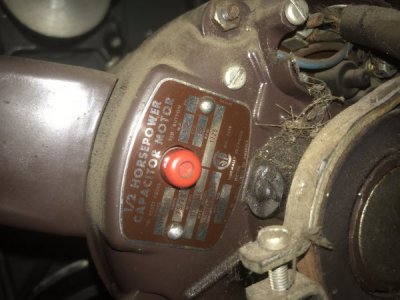
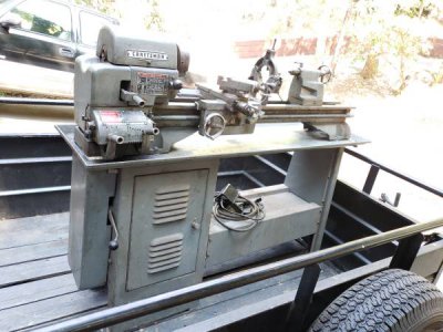
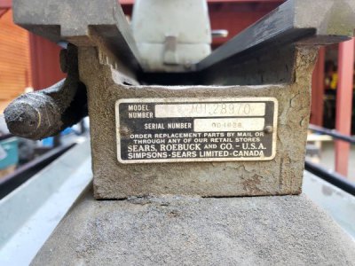
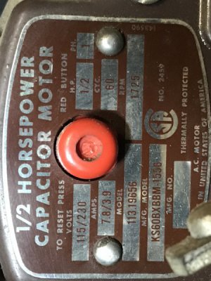
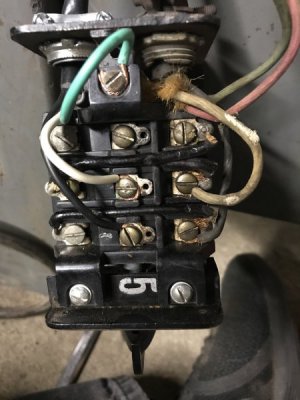
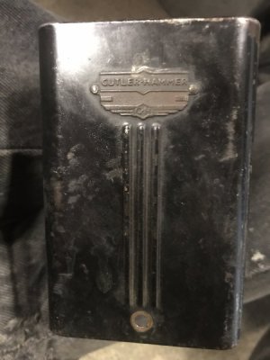
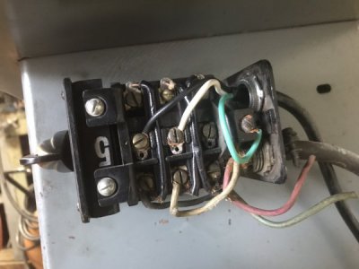
My 101.28970 12 inch Craftsman lathe came with a Craftsman 11319656 1/2 hp motor. The switch provided is a Cutler-Hammer three position switch, fwd, stop and reverse. However it is presently wired just on and off. Can anyone provide a wiring diagram to make it fwd and reverse? I note that there are two wires, a green and a red that are not connected. Can anyone help?
23B6AEE2-2C5B-4F8E-AD2D-291E5732D406.jpeg

3069D396-074D-41AB-A856-815308324B2E.jpeg

01211ECB-84F8-40F4-B2DC-230549BA65F0.jpeg

2DB27304-3984-4412-B049-DE3E69861D24.jpeg

A15DAFD7-B246-4D95-8809-77CC0F2F6DDD.jpeg
 
Don't know about the wiring , but just wondered about the threaded chuck and reverse rotation. By the way I have basically the same lathe. Serves my uses well.
Dave
 
I can’t answer that question yet, but check out the YouTube series by MrPete222 AKA Tubalcain. He has lots of videos showing threading (and just about any operation you can think of) using the Craftsman 12-inch and at least one about indexing the threading processwhere he says reverse is essential.
 
Does the the motor run now as it's currently wired? We would need to look closely at the motor wire terminals to see if the start wires are
accessible- I see it's a dual voltage motor so possibly reversible too.
A close up picture(s) of the motor wiring end would be useful- need to see where those extra wires go (if they go anywhere)
mark
 
Hi Kit,

Can you post a better picture of the motor rating plate ?
 
Does the the motor run now as it's currently wired? We would need to look closely at the motor wire terminals to see if the start wires are
accessible- I see it's a dual voltage motor so possibly reversible too.
A close up picture(s) of the motor wiring end would be useful- need to see where those extra wires go (if they go anywhere)
mark
It does run now. I will need to take the motor out to get a pic of the wiring on the motor side. This will have to wait for the evening as I am at my day job right now. There are two wires from the motor, a red and a green, that are not being used, so I think these are for reverse. I’ll get back to you by tomorrow. Thanks for your help!
 
Hi Kit, I doubt those red and green wires are connected at the motor end- if they were important wires the motor wouldn't run. Anyhow, get some good pictures and we will get a better idea how it should hook up
mark
 
Does the the motor run now as it's currently wired? We would need to look closely at the motor wire terminals to see if the start wires are
accessible- I see it's a dual voltage motor so possibly reversible too.
A close up picture(s) of the motor wiring end would be useful- need to see where those extra wires go (if they go anywhere)
mark
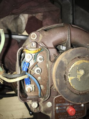
Now that I have the motor out I can see that the green and red wires are snipped at the motor end. There are four terminals in total. A blue wire from the motor goes to T2. A brown wire from the motor goes to T3. A yellow and a blue wire from the motor attach to the T4 terminal which goes to a black wire from the switch, and the white wire from the switch goes to a terminal marked T1. There is nothing else connected to that terminal. I reterminated those two wires after pealing back some insulation to discover their true colors. I have also attached a better pic of the switch. You should be able to see that there are black jumper wires attached from one side of the switch to the other, but the switch only works in one direction.

6FD23B6A-5884-4ECC-A3AF-728D2F004568.jpeg

image.jpg

image.jpg
 
Back
Top