Wiring headaches on my new grinder

hustlebird

H-M Supporter - Diamond Member
H-M Lifetime Diamond Member
Joined
Oct 21, 2021
Messages
63
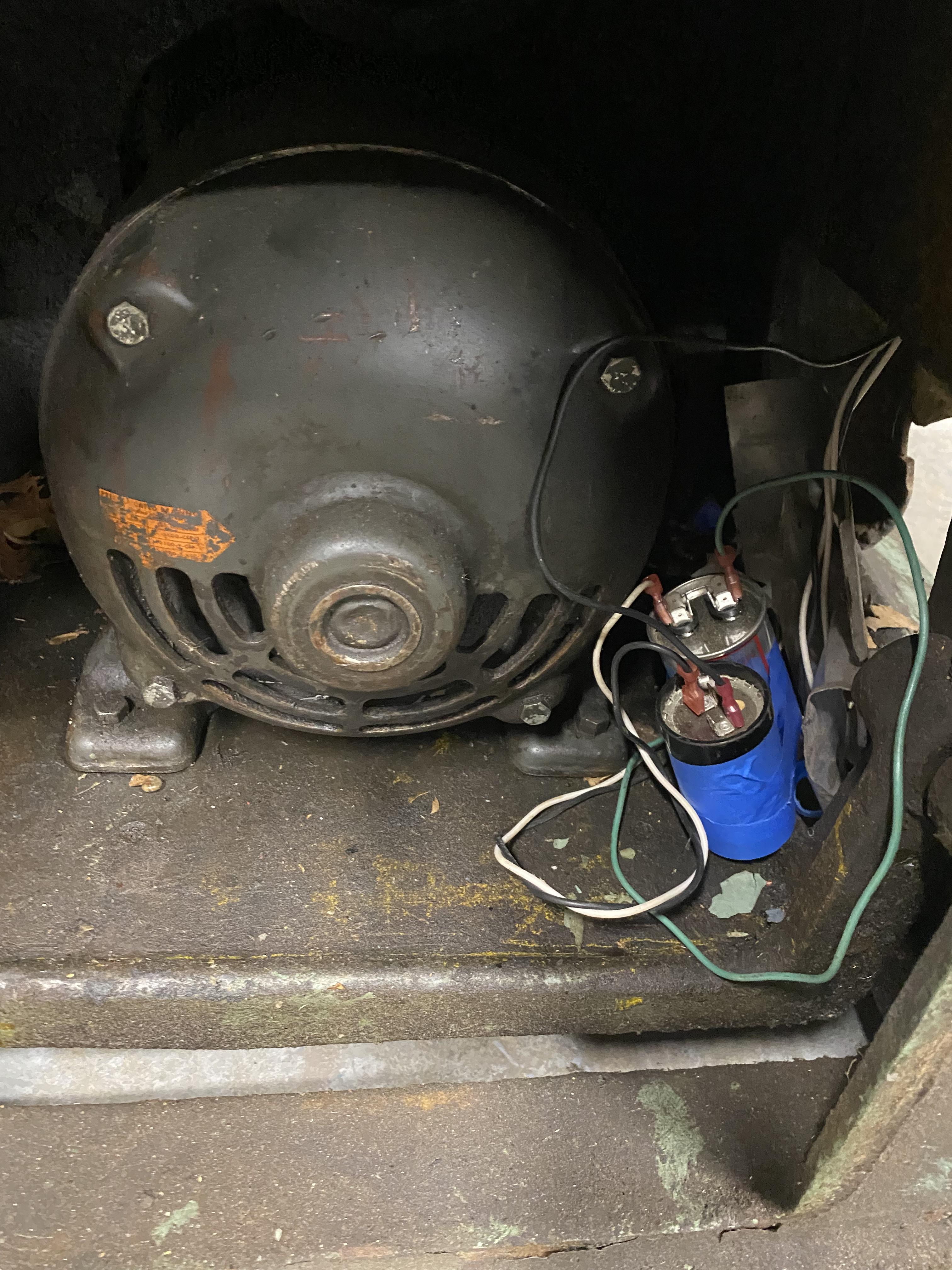
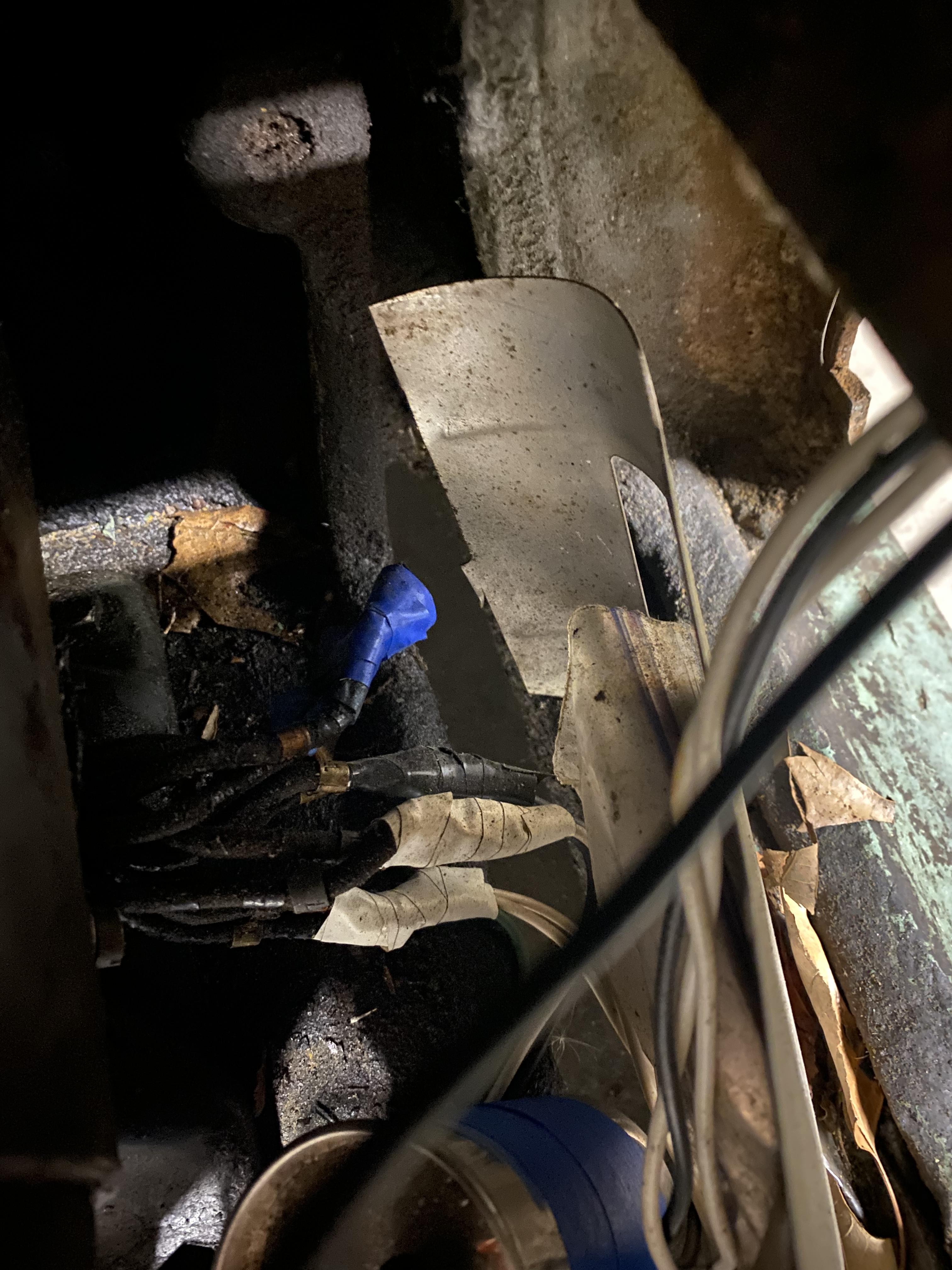
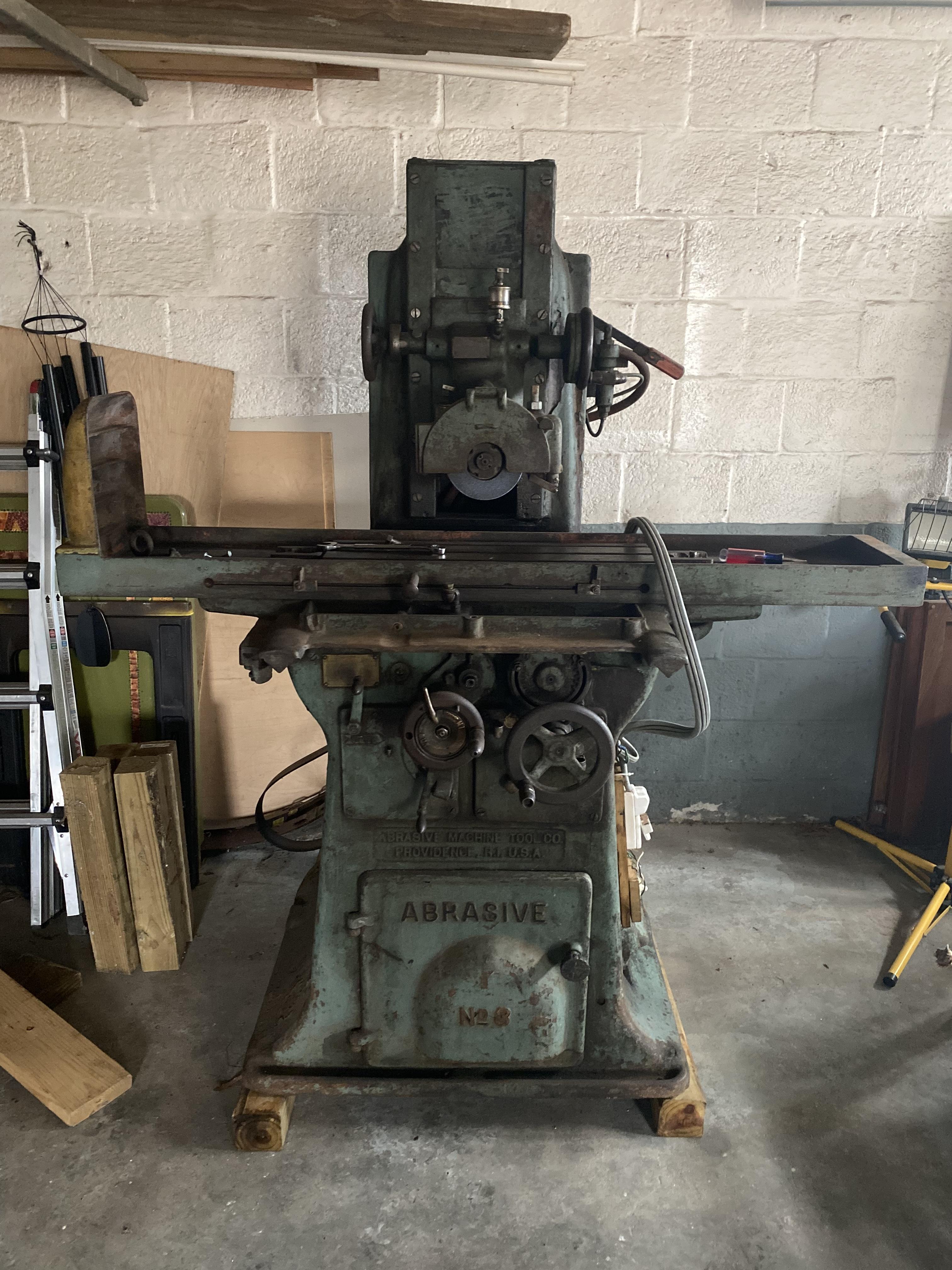
I landed a pretty good deal on an old Abrasive No 3 surface grinder, and managed to get it into the garage today. Unfortunately, the wiring is a hot mess... The guy I bought it from spoke with a heavy accent, but I believe he was saying this is a 3-phase motor, but he wired it with capacitors to run off single-phase. I did see that it runs when you plug it into 220 single-phase, though I'm not inclined to do it again until I get this better sorted.

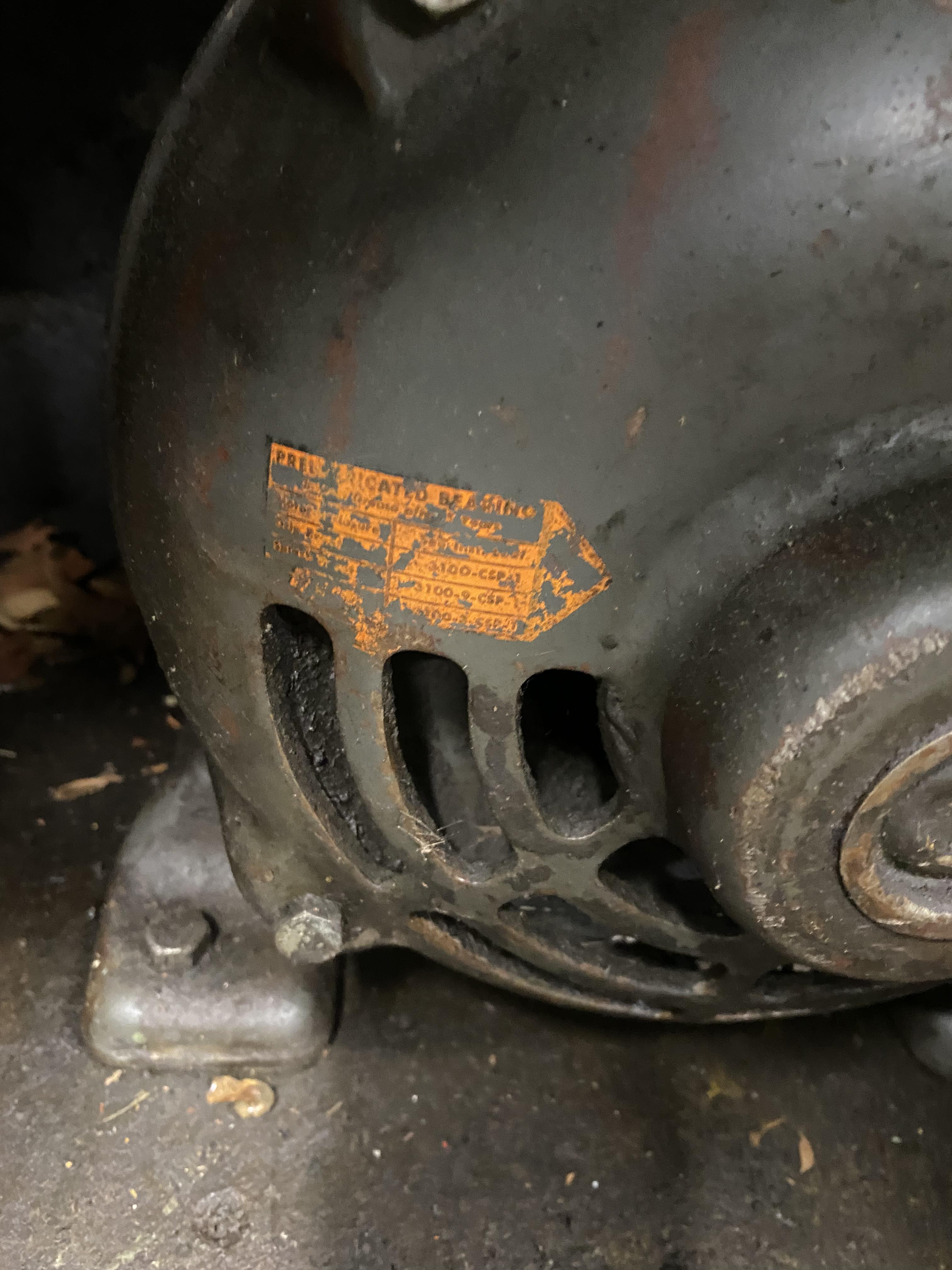
The motor looks gorgeous, but the only sticker that remains on the thing is illegible. Is there anything I can do to determine the size? There's whispers of these No 3 grinders here and there on the internet, but I haven't seen a spec that lays out what sort of sizing and motor I should expect. It looks old, though if its original I'd have no way of knowing.

I do plan to get out there and stretch everything out and hopefully come up with some sort of idea of how its currently wired, but I wasn't in a position to do so tonight, so I just snapped a few pics and was hoping for an easy faceplate readout. So without further ado, here's some pics of the thing:
gM3ef8S.jpeg

kCCYumv.jpeg

p1LEZwB.jpeg
0RWpKHN.jpeg
 
Hopefully the guys who know the language can solve the puzzle.
 
Look at that completely cast iron base.
You will find many surface grinders with heavy gauge sheet metal bases but the best surface grinders were the ones with the cast iron base.
Looks in pretty nice condition including the motor.
Even though the motor looks large my guess is it is 2 hp or less.
Peel open the internet and find you a good 2 Hp VFD. Most will display amperage being output,
 
It looks like a Static Phase Converter set up, a capacitor in parallel between the "Ghost phase" and the each of the split phases (L1&L2). It will work like this but you will only get ⅔ the horsepower. You can convert it to a Rotary Phase Converter by adding in a 3 phase idler motor, a start circuit, and balancing the capacitors, that will get you full power.
You can determine the Hp of the motor by measuring the current the motor is drawing with an ammeter and dividing the total watts by 746.
 
Even though the motor looks large my guess is it is 2 hp or less.
Peel open the internet and find you a good 2 Hp VFD. Most will display amperage being output,
I have an Abrasive 1 1/2 that has a 12" wheel, and it has a 2 HP motor.
I agree with the VFD recommendation. see https://www.hobby-machinist.com/threads/best-programming-instructions-manual-for-xsy-at1-vfd.96036/
Though VFDs may have a little learning curve to do the programming, Once done it requires no thought. I'm completely satisfied with the four I have.
Aaron
 
Generally, the size of the motor can be estimated from the "frame size". It won't give an exact size but should put you in the ball park.

There are several factors that weigh in;
Shaft Size (diameter)
Shaft Height (center to base)
Base Bolt dimensions

The NEMA base pattern will get you close, even if it isn't a NEMA motor.

The orange tag simply refers to the bearings. It implies that the bearings have been replaced and no longer need manual lubricating.

.
 
It looks like a Static Phase Converter set up, a capacitor in parallel between the "Ghost phase" and the each of the split phases (L1&L2). It will work like this but you will only get ⅔ the horsepower. You can convert it to a Rotary Phase Converter by adding in a 3 phase idler motor, a start circuit, and balancing the capacitors, that will get you full power.
You can determine the Hp of the motor by measuring the current the motor is drawing with an ammeter and dividing the total watts by 746.
This is interesting, if I measure the draw with this SPC config running should I make that 2/3's adjustment? Could the capacitors that are in use tell me anything? Maybe just what he thought it was sized like? I have a note of 70uF per kW that I pulled from a youtube video or two I've watched trying to understand how its currently configured. Am I on the right track with that way of thinking?

I have an Abrasive 1 1/2 that has a 12" wheel, and it has a 2 HP motor.
I agree with the VFD recommendation. see https://www.hobby-machinist.com/threads/best-programming-instructions-manual-for-xsy-at1-vfd.96036/
Though VFDs may have a little learning curve to do the programming, Once done it requires no thought. I'm completely satisfied with the four I have.
Aaron
This sounds like the way I will be going. I have/use VFD's for my Lathe and Mill already. The parts doc on Vintage Machinery (This one) actually lists an 8" x 1/2" disc wheel for this thing. See page 13. It looks like the 1-1/2 was a 1/2" disc thickness as well. As an aside - its crazy how old some of these machines are! I was just read about how these grinders can't accomodate 25 cycle current (?!?). And several references to 2-phase current. Back in the beginning days of electricity! Thanks for the info, I think 2hp is probably going to be around the mark for this.

Look at that completely cast iron base.
You will find many surface grinders with heavy gauge sheet metal bases but the best surface grinders were the ones with the cast iron base.
Looks in pretty nice condition including the motor.
Even though the motor looks large my guess is it is 2 hp or less.
Peel open the internet and find you a good 2 Hp VFD. Most will display amperage being output,
I'm pretty excited to take care of this thing and get it going. The No 3B, which is the newer model of this grinder, came with a 3HP motor, so I was starting from that point. It also came with a 10" x 3/4" wheel though (50% bigger), so maybe 2 HP is on the money. I'm going to try and size the capacitors on it, and with the SPC only running at 2/3rds now. I think 2HP may be alright for it. Fortunately I have a 2HP VFD on the way from Wolf Automation sometime eventually, maybe... So If that ever arrives I'll have a home for it.


One thing about the motor, I believe there's 9 wires coming out of the motor here, 3 tied off on blue, and 2 in each set on the white (x2) and black taped pairs. This is vaguely similar / familiar to what I did for my bridgeport, though I don't remember the exact details there. Does that lend credence to the SPC wiring? Again I plan to hopefully chart out everything tonight, as well as finish getting it put back together.

Thanks for all the replys already!
 
Generally, the size of the motor can be estimated from the "frame size". It won't give an exact size but should put you in the ball park.

There are several factors that weigh in;
Shaft Size (diameter)
Shaft Height (center to base)
Base Bolt dimensions

The NEMA base pattern will get you close, even if it isn't a NEMA motor.

The orange tag simply refers to the bearings. It implies that the bearings have been replaced and no longer need manual lubricating.

.
Interesting, thanks for that info about the orange tag. I will try to get that information this evening as I dig through it. On another forum its mentioned that the original motor is an Allis Chalmers motor. Not sure the relevance of that, but it's the only information I have so far :)
 
Back
Top