-
Welcome back Guest! Did you know you can mentor other members here at H-M? If not, please check out our Relaunch of Hobby Machinist Mentoring Program!
You are using an out of date browser. It may not display this or other websites correctly.
You should upgrade or use an alternative browser.
You should upgrade or use an alternative browser.
Wiring headaches on my new grinder
- Thread starter hustlebird
- Start date
- Joined
- Feb 13, 2017
- Messages
- 2,138
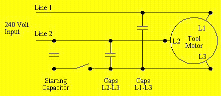
The drawing was quite well done. Your "chicken scratching" would have been fine. As a rotary converter, it is one as is. The only difference between what you have and a true rotary is the capacitor(s). And the switches. . . The capacitors would be split, one for "run", the other as a "kicker" or starting cap. The absolute values will vary from motor to motor so I can't advise what value to use.
Unless you need variable speed, I would not advise a VFD. What you have will work fine, as is. Just replacing the light switches with motor rated relays and a decent enclosure are my only concerns. A "3 wire start" would be a nice addition. And a relay for the kicker should you opt to add one. And, very important, decent insulation on the motor leads. But truth be known, I think you had already seen that. . .
.
- Joined
- Oct 13, 2014
- Messages
- 6,665
It looks like your setup is missing a capacitor to be a proper static converter circuit.

I got that schematic from: a http://www.waterfront-woods.com/Articles/phaseconverter.htm
It was one of the articles I referenced when I did My RPC build, lots of info there and links other builds as well.
I also recommend giving a RPC serious consideration for this application.
To answer your question
"If I measure the draw with this SPC config running should I make that 2/3's adjustment"
That's a good question and I'm not absolutely sure of the answer but my thoughts are yes, if the motor is only putting out 2/3s the HP it will only draw the respective current. Also, the motor will only draw the its maximum current when under load, putting out its full horsepower.
- Joined
- Oct 21, 2021
- Messages
- 63
Thanks again for the wealth of knowledge you've shared. I think for now I will redo the wiring to be safer (fix connectors, replace switches, etc) but leave it as-is while I get to know this tool.The drawing was quite well done. Your "chicken scratching" would have been fine. As a rotary converter, it is one as is. The only difference between what you have and a true rotary is the capacitor(s). And the switches. . . The capacitors would be split, one for "run", the other as a "kicker" or starting cap. The absolute values will vary from motor to motor so I can't advise what value to use.
Unless you need variable speed, I would not advise a VFD. What you have will work fine, as is. Just replacing the light switches with motor rated relays and a decent enclosure are my only concerns. A "3 wire start" would be a nice addition. And a relay for the kicker should you opt to add one. And, very important, decent insulation on the motor leads. But truth be known, I think you had already seen that. . .
.
Everyone recommending the RPC - I hear you, just not something I can swing at the moment unfortunately.
Hopefully some first grinds soon! Appreciate everyone's help and input here.
- Joined
- Oct 21, 2021
- Messages
- 63
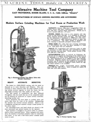
One last addendum for historical purposes. I found this advertisement (https://mycompanies.fandom.com/wiki/Abrasive_Machine_Tool_Company) and it lists / shows the No. 3, and states "When equipped with motor drive, the machine is furnished complete ready for connecting feed wires. A one and a half horse power constant speed motor is used."
@sdelivery - You called it being big for its size

@sdelivery - You called it being big for its size


