

-
Welcome back Guest! Did you know you can mentor other members here at H-M? If not, please check out our Relaunch of Hobby Machinist Mentoring Program!
You are using an out of date browser. It may not display this or other websites correctly.
You should upgrade or use an alternative browser.
You should upgrade or use an alternative browser.
WIRING HELP!! on my newly aquired King model KC401-V2F 3 phase 575
- Thread starter mlalonde
- Start date


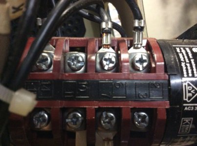
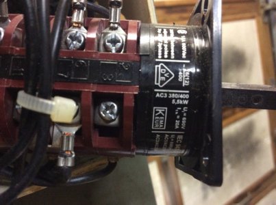
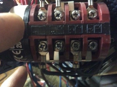
Ok so here is a couple pics of my Drum switch. I also checked every wire and number on the switch. It is as followsMlalonde, can you give me the drum switch manufacture's name, model number, and visible terminal numbers? It may be a little different from the JPM.
The 6 black wires are numbered 1 through 6
No. 1 wire goes to terminal 4 on drum switch
No 2 wire goes to 7
No 3 Wire goes to 12
N0 4 wire goes to 1
No 5 wire goes to 6
No 6 wire goes to terminal13
Theres 3 other black wires that go to the drum..They come from inside the control box.
T1 to terminal 14 on the drum switch
T2 to terminal 2
T3 to terminal 5
Attachments
Last edited:
- Joined
- Feb 2, 2013
- Messages
- 3,625
i thought there were reversing contactors involved with your drill, the pictures prove it!
I don't really want to be the bearer of bad news...
rewiring may be a bit sketchy at best, there will be lots of tracing and identification.
without a wiring diagram from the manufacturer, you have 3 choices (of the top of my head)
A: design your own control system
B: copy a 2 speed reversing contact control system from another manufacturer
C: convert to VFD and run the drill in Wye configuration
option C will be the most expedient method
i thought there were reversing contactors involved with your drill, the pictures prove it!
I don't really want to be the bearer of bad news...
rewiring may be a bit sketchy at best, there will be lots of tracing and identification.
without a wiring diagram from the manufacturer, you have 3 choices (of the top of my head)
A: design your own control system
B: copy a 2 speed reversing contact control system from another manufacturer
C: convert to VFD and run the drill in Wye configuration
option C will be the most expedient method
Thanks Doc
And all because he disconnected the 6 wires?
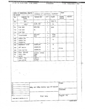
King Canada Gave me this diagram . They said its for this machine. Might make sense to you! Thanks again!!Thanks Doc
And all because he disconnected the 6 wires?
Attachments

- Joined
- Feb 2, 2013
- Messages
- 3,625
Hi @mlalonde ,Thanks Doc
And all because he disconnected the 6 wires?
I was concerned that something is wrong with the drill, as well as otherwise other unknown factors.
if the old owner decided to rearrange control or contactor wiring.
any modification to they systems could present dangers to you.
if were to counsel without certainty that the circuits are identified and wiring in the correct places,
i would be doing you a dis-service.
i would not want to put you in danger, my friend
- Joined
- Feb 2, 2013
- Messages
- 3,625
since you have given a diagram i can better help you
SA1 is the cam switch, it gets 3 wires from FR1 as the power leads (indirectly from the 575v 3 phase power source)
by the diagram SA1 is wired like this
SA1 switch terminal 1 has motor wire 1 attached
" switch terminal 7 has motor wire 2 attached
" switch terminal 12 has motor wire 3 attached
" switch terminal 1 has motor wire 4 attached
" switch terminal 6 has motor wire 5 attached
" switch terminal 13 has motor wire 6 attached
it all appears to be like you said above
Ok so here is a couple pics of my Drum switch. I also checked every wire and number on the switch. It is as follows
The 6 black wires are numbered 1 through 6
No. 1 wire goes to terminal 4 on drum switch
No 2 wire goes to 7
No 3 Wire goes to 12
N0 4 wire goes to 1
No 5 wire goes to 6
No 6 wire goes to terminal13
There's 3 other black wires that go to the drum..They come from inside the control box.
T1 to terminal 14 on the drum switch
T2 to terminal 2
T3 to terminal 5
SA1 is the cam switch, it gets 3 wires from FR1 as the power leads (indirectly from the 575v 3 phase power source)
by the diagram SA1 is wired like this
SA1 switch terminal 1 has motor wire 1 attached
" switch terminal 7 has motor wire 2 attached
" switch terminal 12 has motor wire 3 attached
" switch terminal 1 has motor wire 4 attached
" switch terminal 6 has motor wire 5 attached
" switch terminal 13 has motor wire 6 attached
it all appears to be like you said above
- Joined
- Feb 2, 2013
- Messages
- 3,625
Just a FYI
you'll need to see if the transformer has different(high voltage) taps for the 24v control system
the diagram is for a 380v 3 phase system but your drill should be wired very similar,
but the transformer needs to be set to correct voltage or magic smoke will soon appear.
you'll need to see if the transformer has different(high voltage) taps for the 24v control system
the diagram is for a 380v 3 phase system but your drill should be wired very similar,
but the transformer needs to be set to correct voltage or magic smoke will soon appear.
- Joined
- Feb 2, 2013
- Messages
- 3,625
i'm not seeing a transformer, is it hiding behind the circuit board?
can you give me a clear picture of the board while you are at it?
can you give me a clear picture of the board while you are at it?