Hey everyone,
Struggling a bit on getting my drum switched hooked up on my lathe. I purchased a new 3/4 hp motor - dayton, link below. The switch I have is a 2601AG2 Square D, also link provided.
Dayton D170
In one of schneiders attachments I was able to find a wiring diagram for a 110V split phase motor, but I am a little perplexed on how to do this. Page 4 shows the wiring diagram I am talking about.
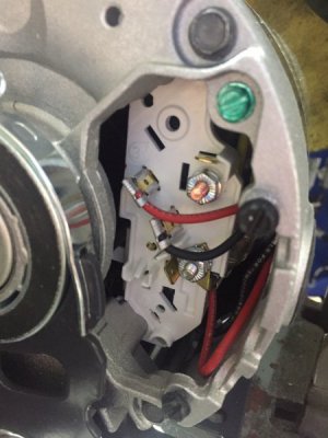
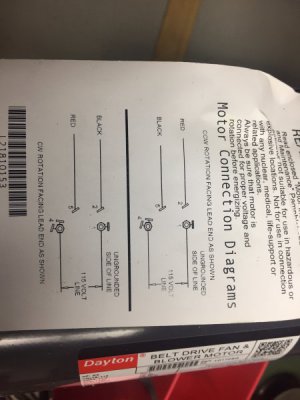
Here are some photos from the motor, as well as a distribution block I plan to use.
I think I've got a pretty good understanding around the functionality of the switch as well as the motor. Where I am stumbling is how each of these makes a connection to eachother. As you can see in the image of the motor, I've got 4 terminals, and two leads into those terminals. What I did here was disconnect the red and black, add a lead to the two terminals they are hooked into (2 and 5) and then ran a lead from the screw terminals (1 and 4). So I've got six leads coming out of my motor, red, black, and terminals 1,2,4,5. Where I struggle is most diagrams I see have only 4 leads coming out from the motor, but this was the only way I could think to be able to physically switch these.
It feels like something minor I am missing. I was able to hook up red and black to my switch and reverse those and prove the motor can switch rotation, I just am not sure how to do this without "hard-wiring" the motor. The issue I was seeing was even in neutral my motor was receiving a voltage as I had ran the voltage lines directly to the motor.
I'd be up for trying different configurations but I'm afraid of the magic smoke...


