- Joined
- May 18, 2016
- Messages
- 2
I was asked to post some detail about my little wiring adventure with a Bridgeport mill. So...
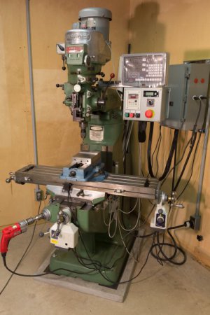
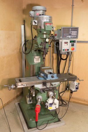
My new (to me) Bridgeport installed. Mill was manufactured in the mid 80’s and was in a prototype lab at Eastman Kodak. It was intercepted prior to auction (as they were going through their death throes) by the machinist who used it. I bought it from the guy he sold it to. In all cases it was only used for prototype development.
The mill was in fantastic shape when I got it. Mechanically, there was very little I needed to do. I suppose I could have removed the god-awful green paint, but for the amount of work involved, I decided to convince myself I like it (its not working). Its a 2HP with chromed ways, a little wear one the Y axis but that was it. I installed new power feeds, and replaced all the tubing and fittings on the one-shot lube. The sump and pump were still good. Runout on the spindle was only 1-2/10 thousandths so I was happy with that.
Once in place I anchored the mill to the floor with sole plates, threaded rod into concrete anchors (Hilti's in my world) and grout. It was leveled within a thousandth or so front to back and side to side. I don't think its going anywhere...
Here is what I did electrically...
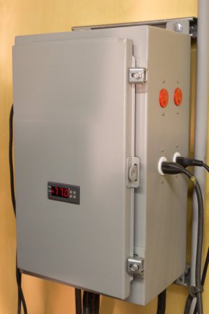
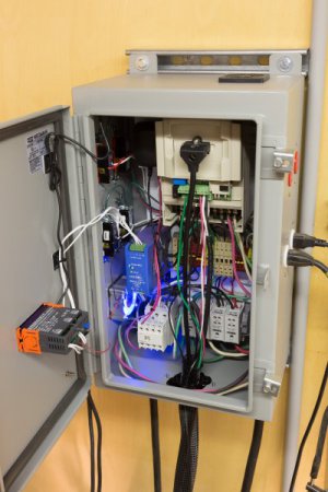
The main panel on the wall is fed with 30amp 220v power from the electrical panel. On the bottom right of the panel are 4 distribution blocks. One each for the 2 hots, 1 neutral and 1 ground. The 2 hots and the neutral are fed to the magnetic switch on the bottom left. Power from there is then run to terminal blocks. They are red, in the middle right of the panel. The yellow things are jumpers for the blocks. Power from the magnetic switch is sent through the terminal blocks to the variable frequency drive in the upper right of the panel. The two hots are also split, combined with a neutral and are used to power the red outlets on the side of the cabinet. There are two red outlets and each side of the cabinet. Each pair is one circuit. The emergency stop is wired to magnetic switch. The hots to the outlets are fused at 15amps (those are the beige terminal blocks near the red ones). The grounds are yellow and green and they are connected to each other through the DIN mounting rail. The backpanel, the DIN rail and enclosure are all grounded.
The result is that when the emergency stop is pressed, power is shutoff to the VFD and the red outlets (there are four of them, on two different circuits, two on each side of the cabinet). I'm a novice at machining and wanted to be sure I had a way to stop everything if I had to panic!
The power distribution blocks also send 120v (one hot) to four other fused terminal blocks. Two of them are for the white outlets (again two outlets on each side of the cabinet). These are also paired with the appropriate neutrals and grounds. The result is the white outlets stay powered up even if the emergency stop is pressed. I will use these for lights, etc.
The remaining two 120v feeds go to transformers. The blue one, middle left, provides 12v DC power to temperature sensor and fan. This keeps the interior cabinet temperature stable. The other one powers a 120v outlet (upper right) that has a 9 volt transformer plugged in. It sends power to the tachometer on the auxiliary panel.
The auxiliary panel is mounted to an articulated arm. It has start, stop, forward/reverse, speed control and emergency stop controls Everything is wired the VFD except the emergency stop (as noted above, wired to magnetic switch). On the upper left of the auxiliary panel is the speed drive control panel and the display shows frequency. The tachometer on the upper right shows either RPM of the spindle or SFPM of the cutter. The tach uses an optical reader that is mounted to the top of the spindle. There is no draw bar because the spindle is Kwik Switch 200.
The tachometer is from MachTach and is sold as a kit. It is easy to assemble, if a little tedious with all the soldering required. I'm not very good at it and managed to get together and working first time. The VFD is a CV7300 from FactoryMation (as are most of the panel components). I'm not trying to advertise here, but they were extremely helpful with wiring questions and also setting the various parameters for the drive. If you haven't dealt with one of these VFD's be forewarned, there a a LOT of variables you can set.
Above the auxiliary panel is the very nice and cheap Chinese DRO. Less than 300 bucks, including shipping. Has a display for X, Y and Z axis. You get what you pay for I guess as the manual is impossible to decipher, but quite funny. I'm still trying to figure a bunch of things out but I am slowingly making their (that's a joke...).
Between the controls, VFD, panels, power feeds, DRO, lube parts, moving the machine to my place (its in a basement, BTW) and misc. stuff I guess I put about 3k into the machine. Got it for 3k so as it sits in the photo I have about 6k into it. It came with a bunch of tooling (Kwik Switch stuff) and raw materials that aren't shown.
If you have any questions (I hope this wasn't too confusing)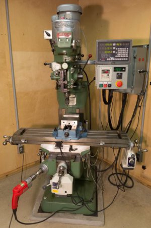
 feel free to ask...


My new (to me) Bridgeport installed. Mill was manufactured in the mid 80’s and was in a prototype lab at Eastman Kodak. It was intercepted prior to auction (as they were going through their death throes) by the machinist who used it. I bought it from the guy he sold it to. In all cases it was only used for prototype development.
The mill was in fantastic shape when I got it. Mechanically, there was very little I needed to do. I suppose I could have removed the god-awful green paint, but for the amount of work involved, I decided to convince myself I like it (its not working). Its a 2HP with chromed ways, a little wear one the Y axis but that was it. I installed new power feeds, and replaced all the tubing and fittings on the one-shot lube. The sump and pump were still good. Runout on the spindle was only 1-2/10 thousandths so I was happy with that.
Once in place I anchored the mill to the floor with sole plates, threaded rod into concrete anchors (Hilti's in my world) and grout. It was leveled within a thousandth or so front to back and side to side. I don't think its going anywhere...
Here is what I did electrically...
The main panel on the wall is fed with 30amp 220v power from the electrical panel. On the bottom right of the panel are 4 distribution blocks. One each for the 2 hots, 1 neutral and 1 ground. The 2 hots and the neutral are fed to the magnetic switch on the bottom left. Power from there is then run to terminal blocks. They are red, in the middle right of the panel. The yellow things are jumpers for the blocks. Power from the magnetic switch is sent through the terminal blocks to the variable frequency drive in the upper right of the panel. The two hots are also split, combined with a neutral and are used to power the red outlets on the side of the cabinet. There are two red outlets and each side of the cabinet. Each pair is one circuit. The emergency stop is wired to magnetic switch. The hots to the outlets are fused at 15amps (those are the beige terminal blocks near the red ones). The grounds are yellow and green and they are connected to each other through the DIN mounting rail. The backpanel, the DIN rail and enclosure are all grounded.
The result is that when the emergency stop is pressed, power is shutoff to the VFD and the red outlets (there are four of them, on two different circuits, two on each side of the cabinet). I'm a novice at machining and wanted to be sure I had a way to stop everything if I had to panic!
The power distribution blocks also send 120v (one hot) to four other fused terminal blocks. Two of them are for the white outlets (again two outlets on each side of the cabinet). These are also paired with the appropriate neutrals and grounds. The result is the white outlets stay powered up even if the emergency stop is pressed. I will use these for lights, etc.
The remaining two 120v feeds go to transformers. The blue one, middle left, provides 12v DC power to temperature sensor and fan. This keeps the interior cabinet temperature stable. The other one powers a 120v outlet (upper right) that has a 9 volt transformer plugged in. It sends power to the tachometer on the auxiliary panel.
The auxiliary panel is mounted to an articulated arm. It has start, stop, forward/reverse, speed control and emergency stop controls Everything is wired the VFD except the emergency stop (as noted above, wired to magnetic switch). On the upper left of the auxiliary panel is the speed drive control panel and the display shows frequency. The tachometer on the upper right shows either RPM of the spindle or SFPM of the cutter. The tach uses an optical reader that is mounted to the top of the spindle. There is no draw bar because the spindle is Kwik Switch 200.
The tachometer is from MachTach and is sold as a kit. It is easy to assemble, if a little tedious with all the soldering required. I'm not very good at it and managed to get together and working first time. The VFD is a CV7300 from FactoryMation (as are most of the panel components). I'm not trying to advertise here, but they were extremely helpful with wiring questions and also setting the various parameters for the drive. If you haven't dealt with one of these VFD's be forewarned, there a a LOT of variables you can set.
Above the auxiliary panel is the very nice and cheap Chinese DRO. Less than 300 bucks, including shipping. Has a display for X, Y and Z axis. You get what you pay for I guess as the manual is impossible to decipher, but quite funny. I'm still trying to figure a bunch of things out but I am slowingly making their (that's a joke...).
Between the controls, VFD, panels, power feeds, DRO, lube parts, moving the machine to my place (its in a basement, BTW) and misc. stuff I guess I put about 3k into the machine. Got it for 3k so as it sits in the photo I have about 6k into it. It came with a bunch of tooling (Kwik Switch stuff) and raw materials that aren't shown.
If you have any questions (I hope this wasn't too confusing)


 feel free to ask...


 Steve Shannon