-
Welcome back Guest! Did you know you can mentor other members here at H-M? If not, please check out our Relaunch of Hobby Machinist Mentoring Program!
You are using an out of date browser. It may not display this or other websites correctly.
You should upgrade or use an alternative browser.
You should upgrade or use an alternative browser.
Wondering if someone can look at my grounding
- Thread starter mkeller
- Start date
Hooking up my vm. I have 220 going to my 20 hp rotary phase converter going to my vm.
At the power box 220 white is grounded.
I drove a 8 foot copper rod in the ground at the phase converter and grounded the convertor panel and generator.
generator wiring white ground goes to panel and ties into ground rod wire.
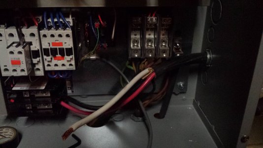
pic of 3 phase panel, Question 1 should I tie the 220 white ground in to the ground rod wire?, ground going to ground rod is bottom right black wire.
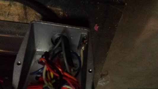
pic of vm power box .Question 2 . 3 phase Power cable going two the vm is grounded to ground rod at panel. Should the other end tie into a ground in the vm panel. Im thinking the small green wire behind the power cabel?
Im sure this is clear as mud so feel free to ask for any more info or pictures.
Thanks
mike
![20140320_193834[1].jpg 20140320_193834[1].jpg](https://www.hobby-machinist.com/data/attachments/33/33221-96a195a7c84a19f27bae69414ec3c470.jpg)
- Joined
- Jan 22, 2011
- Messages
- 8,031
The condensed answer, if I understand your question correctly, is that earth ground and bonding to the neutral only is permitted at the service panel. Equipment ground, like to a frame or chassis is done at the machine, but not with the neutral. The neutral can be a current carrying conductor in some cases, and positively is in others and should never be connected to the machine frame or chassis. It may seem counter intuitive, but electrically, the earth ground and the neutral are only at exactly (hopefully) the same potential at the service panel only. That is even if they are two separate wires in the same conduit running from the same box to the same equipment. The ONLY point where they are common is at the entrance panel.
Now all the real electricians can correct me and explain in more detail.
Now all the real electricians can correct me and explain in more detail.
- Joined
- Jun 17, 2012
- Messages
- 2,220
Tony is correct in his description of the neutral and ground should only tie together back at the main service entrance or sub panel. The bare copper wire or Green sheathed wire should be designated as your ground wires for bonding boxes and machinery.
In your photo, you are showing the ground wire hooked up as your third leg on the 3ph circuit. For safety sake change that. This probably means that you'll have to change it at both ends of your wire. The white wire should be carrying voltage in a 3ph circuit. Whit only carries neutral in a single phase circuit. Neutral is not used in a 3ph circuit.
Marcel
- Joined
- Mar 10, 2013
- Messages
- 1,428
The main entrance service panel from the power company is the only place that white(neutral) wires are connected to the ground--in all other sub panels and on machines-- neutral wires have their own separate bar and the screw to connect the neutral to the box is removed and the grounds have their own bar--neutrals are always kept separately from the ground wires and carry any voltage back to the main panel only---hope this clears it up for you---any ground rods would only be connected to the grounding wires------Dave
**I agree with Marcel that in three phase the white wire is used as the third leg of power.
**I agree with Marcel that in three phase the white wire is used as the third leg of power.
- Joined
- Nov 23, 2013
- Messages
- 593
It looks like non-metalic sheathed cable feeding the converter control box. That should have had a bare ground wire in it that should be connected to the equipment ground terminal at the converter and the ground or ground/neutral bar in the service panel depending on how your service is arranged. Do not connect the white neutral wire to the frame of the machine as it could create an unsafe condition. Shocks or fires are possible. The ground rod you installed must also be connected to the equipment ground. You can't just drive a ground rod and use it as a ground without bonding it to the service ground. The earth has too much resistance to reliably carry fault currents or protect you from a shock. Shocks are caused by a difference in potential between two points not necessarily voltage. Also NEVER use the green as a current carrying conductor. Tape the white wire blue or better yet cover it with shrink tube. If that is the "manufactured" phase it is supposed to be identified with it's own color by code similar to using orange on the "high" leg of a 240v delta service. Connect the green in that cable to the frame of each machine or grounding lugs in the cabinets.
- Joined
- Sep 11, 2012
- Messages
- 329
After I read all the posts three times through to be sure of what I was reading I must remark, all you guys trying to help Mkeller are correct. Well correct in your own way and intentions best I can tell.
Let me throw a term at you electricians use to separate out what you are trying to say so they can understand it. BONDING. Bonding is the term used when you make physical hard wire connections to ensure the electrical path to ground through devices in the path to the point of ground. When the fellow connected to the ground rod at the RPC he bonded it, not grounded it. When you join two enclosure together with ground wire, grounding locknuts, or grounding bushings you are BONDING the enclosures together not grounding them. The neutral bar in the main service panel is BONDED to the enclosure. Use this term to explain what you are up to and any electrician you talk to will know exactly what you are talking about. This applies to the point that each of you was trying to make in your own way.
BOY! I used to take for granted the green wire was either connected to a grounding point or hanging free so never checked it for voltage. After seeing this I will change my habits. I ALWAYS check for the presence of voltage on anything I intend to lay my pinkies on. I always say "I would not even trust my mother if she said the circuit is off!" Yes, definitely, identify that white conductor and disconnect that green one from the disconnect lug. Remember the other end too!
One last nit pick. A five wire circuit is rather common place. Mostly in industrial establishments. Three phase conductors, neutral, and ground. Cords, cord ends, plugs, receptacles etc are all readily available from the electrical supply warehouse. Common configurations 480/277v Wye, 240/120v Delta, and 208/120v Wye. The good book clearly (almost) lays out the use and application of this type circuitry.
You can not ground anywhere you choose as you will create ground loops which will cause more trouble then anyone needs. This is when the electricity, as usual, takes the path of least resistance to ground and that may not be the electrical system ground. If you are working in a panel that does not have a meter directly ahead of it, you are more than likely in a sub-panel and the neutrals and grounds shall remain separated. Only in the service entrance panel do they come together.
Confused enough for one night? Good, my work is done.
Well i guess we know why im a tool and die maker and not an electrician. I will go back to square one. with a little more help from the site here.
My power is a 200 amp service to my house and a wire runs underground to my shed to a smaller service box.
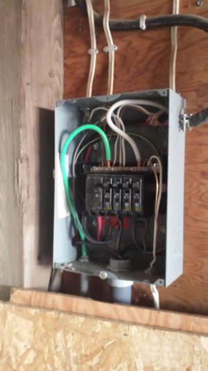
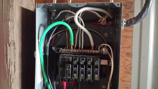
heres the shed service box
wire running the machine is the top right
The shed had existing 220 wire run
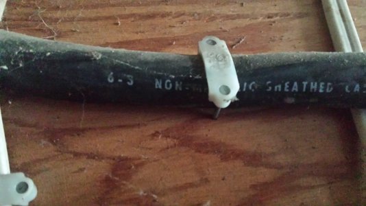
So first new question, Is the 220 wire correct for what im doing? its probaly 30 35 feet long. Should it be in conduit(sp) I would like to do this correctly(without paying a professional)
if it is ok then question 2
how should i hook it up to L1 and L2
going to call the rotary phase people as well and see if they can help.
Thanks again and your welcome for the noobie humor
Mike
- - - Updated - - -
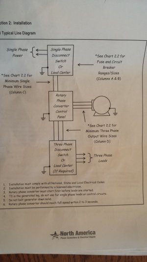
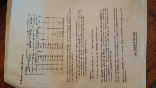
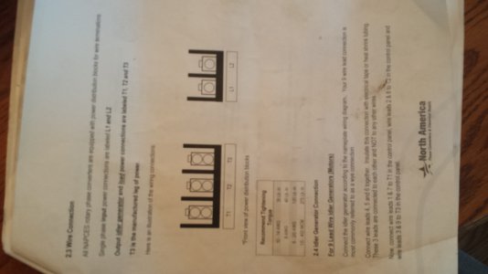


My power is a 200 amp service to my house and a wire runs underground to my shed to a smaller service box.
heres the shed service box
wire running the machine is the top right


The shed had existing 220 wire run

So first new question, Is the 220 wire correct for what im doing? its probaly 30 35 feet long. Should it be in conduit(sp) I would like to do this correctly(without paying a professional)
if it is ok then question 2
how should i hook it up to L1 and L2
going to call the rotary phase people as well and see if they can help.
Thanks again and your welcome for the noobie humor
Mike
- - - Updated - - -


- Joined
- Dec 8, 2013
- Messages
- 2,651
If your shed is a seperate building the panel there is a service entrance and should be bonded and grounded as such.
If you use a white wire to carry voltage mark it at both ends. I like to color all exposed parts of the wire with magic marker. You want to minimize the risk that someone in the future will mistake it for a grounded conductor.
If you use a white wire to carry voltage mark it at both ends. I like to color all exposed parts of the wire with magic marker. You want to minimize the risk that someone in the future will mistake it for a grounded conductor.
- Joined
- Sep 11, 2012
- Messages
- 329
Good Sir:
From the pictures in your post of the sub panel in your shed you need to move a few wires. Get a separate ground bar from SqD. It will look just like the neutral bar sans the insulating block. Screw this ground bar directly to the box. Scraping paint off the box where the bar lands is good practice also. Now move all the bare wires from the neutral bar to the ground bar. Include the big green wire, where ever it comes from. Check to see that there is NOT a screw going through the neutral bar into the enclosure. If there is, remove it. This is what is called the neutral bonding screw and should only be installed in a main service entrance panel. All other places the grounds and neutrals must be kept isolated from each other.
The neutral is the electrical ground and carries the unbalance in the circuit between the phase conductors. The ground is the equipment safety ground and is only meant to carry fault current for indefinite short periods of time.
Have FUN, be SAFE!

