X axis power feed for 6x26 knee mill

MontanaLon

Registered
Registered
Joined
Mar 15, 2019
Messages
708
I have been toying with getting a power feed for the x axis on my HF knee mill and looking at all the options I haven't seen one that will be "plug and play" for my machine. Everything I see online has a "Bridgeport" mounting block to go on the table so I would have to create something to attach the power feed in place.

Anyone ever done a power feed on their HF knee mill using off the shelf parts or with some modifications? Be interested to see your project and pick your brains about it.
 
I have a similar mill from busy bee, and on it I got the power feed meant to be put on a round column mill. The way that it clamps is a more universe than the Bridge port right side feed that hangs. still needed to modify the clamp configuration and add an aluminum spacer, but it is all square construction.
 
I have a similar mill from busy bee, and on it I got the power feed meant to be put on a round column mill. The way that it clamps is a more universe than the Bridge port right side feed that hangs. still needed to modify the clamp configuration and add an aluminum spacer, but it is all square construction.
I have seen that style and wondered how I could make it work. I'd have to make a coupler to go on the lead screw shaft to integrate it into the keyway to drive the lead screw. It is definitely an option but if I can keep the hand wheels on both ends I would like to keep them both. Having 2 is handy when I am working with my son so I can keep his speed under control from the other end.
 
If you are teaching your son to machine, than it may be best to ignore the power feed all together, the power feed is an item of convenience and productivity, not versatility. Spend the money fixtures, measuring tools or cutters.
 
I have been toying with getting a power feed for the x axis on my HF knee mill and looking at all the options I haven't seen one that will be "plug and play" for my machine. Everything I see online has a "Bridgeport" mounting block to go on the table so I would have to create something to attach the power feed in place.

Anyone ever done a power feed on their HF knee mill using off the shelf parts or with some modifications? Be interested to see your project and pick your brains about it.

Hi MontanaLon,

I just completed a X axis power feed on my HF 626 two months ago. You will need a lathe to make a shaft extension to the lead screw. The other issue is to be able to cut a 5mm key way slot in the brass gear hub from the power feed kit. I used my lathe as a manual shaper to cut the internal keyway in the bore. You could fore go the internal key way and mill a flat on the lead screw shaft and tap a set screw in the brass gear hub. I'll take some pictures tonight and show you what I did if you want to go my direction.
~John
Excellent, thank you.
 
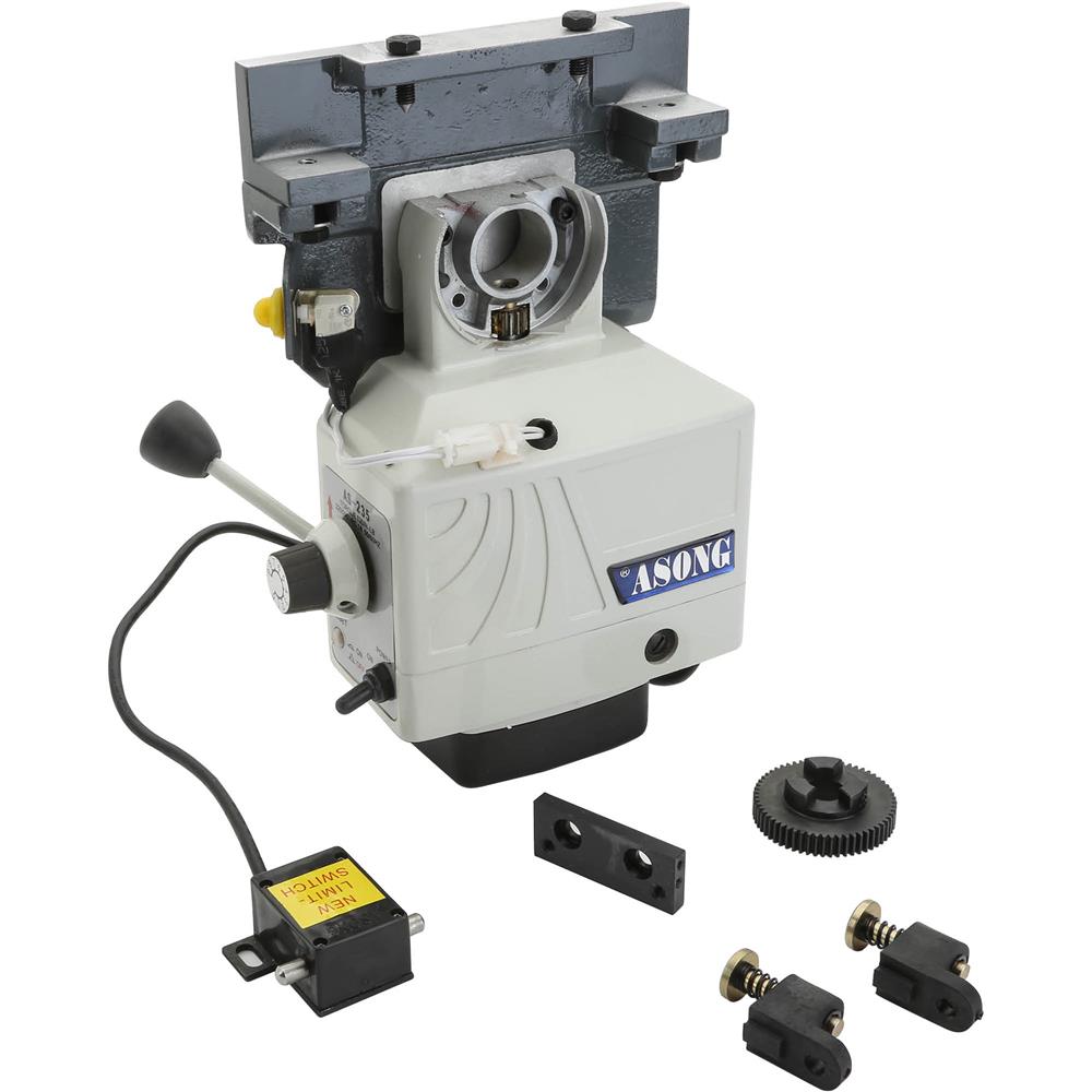
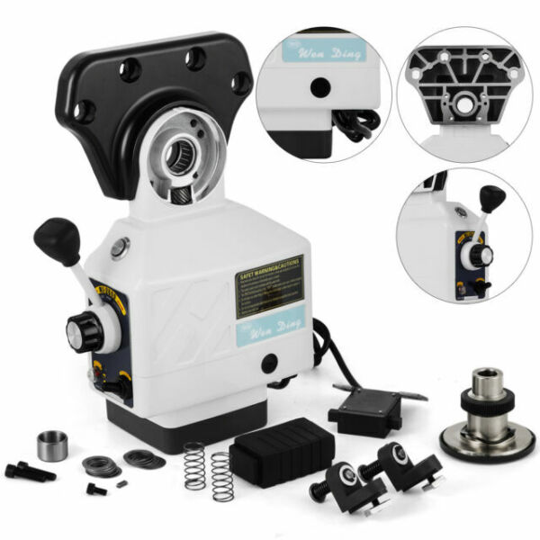
This is the power feed I used:

To install X axis power feed to HF626 mill and keep hand wheel.
Steps:

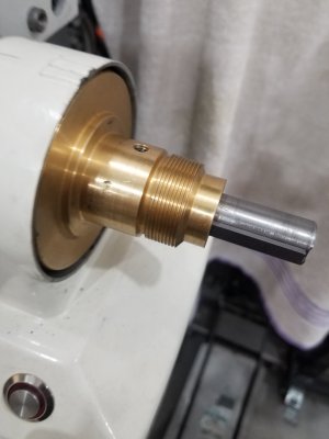
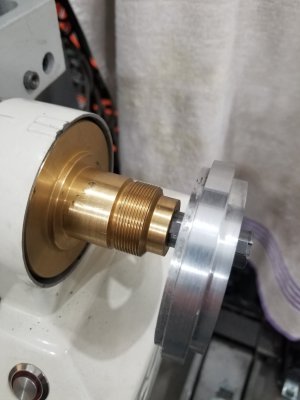
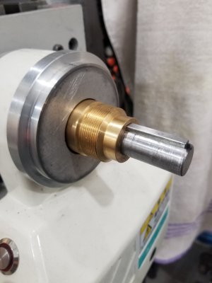
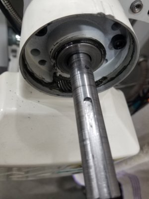
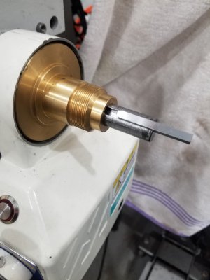
1. Need to extend the x axis lead screw shaft by 3.188"( 4.188" Overall length). if you follow this setup. You need to turn a 1 inch long reduced diameter on this stub shaft to insert into a bore that you will drill into the existing lead screw shaft. I don't recall what the diameter of this bore was, approx. 3/8". But you need to be careful so there is enough wall thickness around the bored hole for strength and dowel pin.
2. I made the bore a slip fit (0.001") to the stub shaft. Use a lathe for minimal runout.
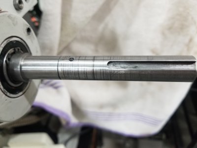
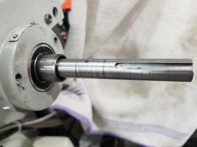
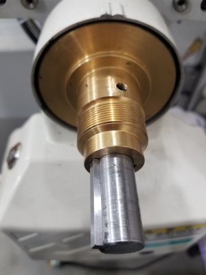
3. Mill the 5mm keyway.
4. I cross drilled the stub shaft and lead screw shaft when assembled for a 1/16 dowel.
5. Assembled stub shaft to lead screw shaft with loctite sleeve retaining compound and pressed the dowel in with it as well.
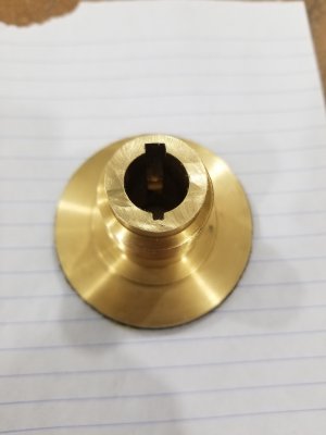
6. Machine a 5mm keyway in the brass gear hub from the power feed kit. The hub comes with a small keyway already but its too small. The 5mm keyway does not need to go the entire length of the gear hub. About an 1 inch or so is good. I used the lathe and cross feed as a manual shaper and slowly cut the keyway. Check out youtube on this.
7. I also drilled and tapped a M5 set screw hole into the gear hub. (I milled a small flat on the lead screw shaft for this as well). This set screw will allow you to set the engagement of the brass gear into the pinion gear on the power feed housing and keep it there.
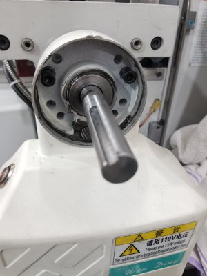
8. Assemble the lead screw w/stub shaft into the mill. You will notice there is approx. 5/8 of the shaft past the c-clip near the table bearing housing. Put the caged needle bearing from the kit on this and hang the power feed unit. Locate two M6 capscrew holes and drill/tap them into the table bearing housing. This secures the unit to the table. (Once mounted, I found there was no need for the caged needle bearing but I left it in.)
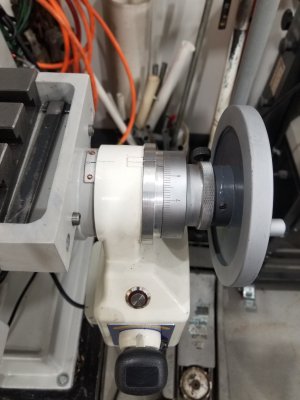
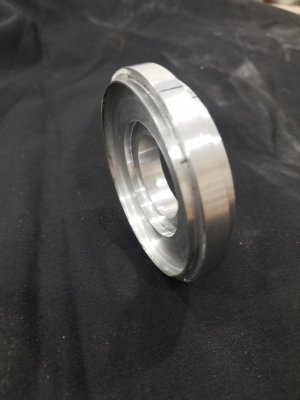
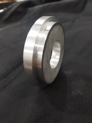
9. I made an aluminum trim ring to enclose the brass gear hub and give the handle dial a surface for it to mate against. It slip fits into the power feed housing and has enough clearance around the brass gear. It is a tight fit. I use a little RTV silicone to hold the aluminum trim ring in place and not turn with the dial.
10. With the trim ring in place, just slip on the handle and secure with the set screw.
 

Attachments

  • 20200406_191943.jpg
    20200406_191943.jpg
    1.1 MB · Views: 114
  • 20200406_193156.jpg
    20200406_193156.jpg
    1.3 MB · Views: 95
  • 20200406_191626.jpg
    20200406_191626.jpg
    1.4 MB · Views: 88
  • 20200406_191918.jpg
    20200406_191918.jpg
    1.2 MB · Views: 78
  • 20200406_193035.jpg
    20200406_193035.jpg
    1.4 MB · Views: 76
  • 20200406_193044.jpg
    20200406_193044.jpg
    1.4 MB · Views: 75
  • 20200406_191847.jpg
    20200406_191847.jpg
    1.2 MB · Views: 74
  • 20000821_192143.jpg
    20000821_192143.jpg
    1.1 MB · Views: 84
  • 20000821_192347.jpg
    20000821_192347.jpg
    3 MB · Views: 87
  • 20000821_192508.jpg
    20000821_192508.jpg
    2.9 MB · Views: 78
  • 20000821_192605.jpg
    20000821_192605.jpg
    1.1 MB · Views: 78
  • 20000821_192716.jpg
    20000821_192716.jpg
    941.4 KB · Views: 73
  • 20000821_192759.jpg
    20000821_192759.jpg
    1.3 MB · Views: 74
  • 20000821_192846.jpg
    20000821_192846.jpg
    1.1 MB · Views: 86
Sorry. One edit.... I used a 1/8" dia. dowel. not a 1/16" dia. for the cross drilled pin.
 
Sorry. One edit.... I used a 1/8" dia. dowel. not a 1/16" dia. for the cross drilled pin.
Wow, thank you, that is an awesome write up and pictures. I may be back with more questions. Looks like I should have the power feed before the weekend. Not a whole lot going on around here so with luck I may get to work on it over the weekend.
 
Back
Top