X2 Mill Limit Switch Locations

papermaker

Active User
Registered
Joined
Mar 12, 2013
Messages
302
Still working on my LMS CNC conversion.I want to hard wire limit switches and I'm stuck for ideas about where to locate the switches. Does anyone have pictures of how you mounted yours. Also still struggling with how to set up the homing in the Mach 3 software. I had a friend over that recently graduated from technical school and is now employed as a machinist and he was having trouble understanding it!:dunno:
 
Hi papermaker
I'll try to help with mach3 and how it handles limit switches. normally with a single parallel port your number of pins left for non stepper/servo motor functions is 4 and one of those will be used for the emergency stop. this leaves you with three remaining. To save pins for other functions like motor control mach3 can be set up to use one pin for all the limit switches. this is done by wiring the switches in series from one switch to the next. mach3 will know what switch it triggered by the direction it was telling the axis to go when the switch was triggered.
I hope that helps
steve
 
I've got to install limit/home switches on mine as well, so I'm interested in the suggestions. I did read where users wer installing one limit switch per axis and using pins at the travel limits to trip the switch, much like a hard stop works. I was initially thinking 2 switches per axis and, as usual, was over-complicating things.

Wish I could help with the software. I'm still struggling with tool radius compensation and offsets. :thinking:
 
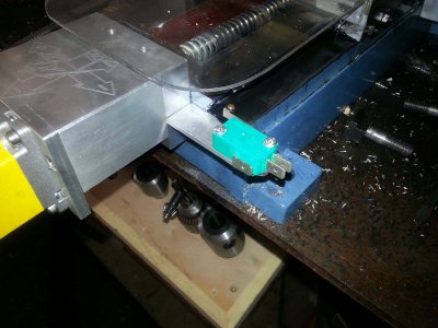
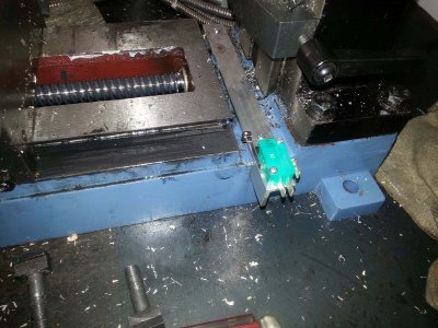
I'll post a picture of what I've got done so far. I put 2 limit switches on the "Y" axis.
I can't seem to get mine to home consistently. I think having the machine coordinates and the work coordinates on the same button is what is getting me confused. And I guess that you have to reboot the computer if you re-home the mill. I've yet to make chips with the new system. Beginning to wonder if I ever will. Not really!
 
Hi papermaker
I'll try to help with mach3 and how it handles limit switches. normally with a single parallel port your number of pins left for non stepper/servo motor functions is 4 and one of those will be used for the emergency stop. this leaves you with three remaining. To save pins for other functions like motor control mach3 can be set up to use one pin for all the limit switches. this is done by wiring the switches in series from one switch to the next. mach3 will know what switch it triggered by the direction it was telling the axis to go when the switch was triggered.
I hope that helps
steve

If you wire all the switches in series on a single circuit, as soon as you brake contact with any switch you lose all contact when in series. Each will need to have its own output for each axis from a common power source. Tim

- - - Updated - - -

Here's the pictures.
You should use enclosed switches and sealed contacts. A single chip will ruin your day if it grounds or shorts out. Tim
 
tim
mach3 knows the direction it is telling the axis to move so it knows what switch was opened. that's how they can be wired in series and still work.
steve
 
If you wire all the switches in series on a single circuit, as soon as you brake contact with any switch you lose all contact when in series. Each will need to have its own output for each axis from a common power source. Tim

- - - Updated - - -


You should use enclosed switches and sealed contacts. A single chip will ruin your day if it grounds or shorts out. Tim

I agree one chip will mess things up. I suggest using heat shrink tubing long enough to cover the contact and at least 1/2" of the wiring. The best with your project.
 
Back
Top