Yet ANOTHER treadmill conversion...

Shepherd

Registered
Registered
Joined
Oct 27, 2011
Messages
50
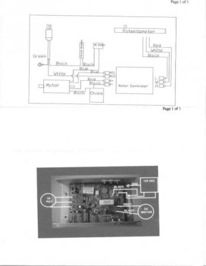
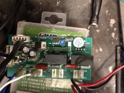
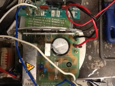
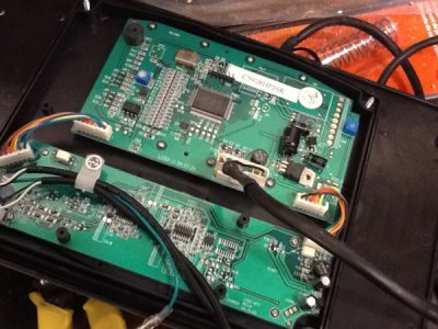
image.jpeg image.jpeg image.jpeg image.jpeg For a belt grinder, got it all reconnected and working with the original display....my question for all the electrictronic magicians is this:

Where in this godforsaken mess could I connect a pot dial and an on off switch to do away with the monster sized digital display and controls? The wide paddle connection is the one from the control panel....was hoping there was an easier way than cutting that open and using trial and error....
 
Hey keep me in the loop. I have an old giant treadmill in my storage container another job or project to use it on. I'm thinking it for a belt sander build or drill press. But sure takes up a ton of room so I've got to dismantle it. Broken down in parts it 'll store easier. Steel to use , motor and controller. Even the belt to make tracks for my wheelchair . I'm a repurposer With a has much as I can. Might help to mark where the pot hooks up I would guess it could be done with a different pot and switch , may even be reversible with the right power switch.
 
Last edited:
Most likely you could check for voltages on the wires connecting the motor drive board to the control board as you vary the speed. If it's a varying voltage you might get lucky, and hack it with a potentiometer but more likely it's a PWM interface like the MC-2100 board uses so you'd need to generate that signal within the parameters the motor driver expects. To figure that out you'd probably need an oscilloscope and the electronics knowledge to use it.
 
OK, I'm following you...just clarify that bit after you said "Most Likely"....

In all seriousness, I figured I could start checking the individual wires from the console, but I wasn't sure if there was any logic/ processes eps the speed controller would be dependent on...also, the con olé requires you to start the motor, then ramp up the speed, so not sure how that would wire in....
 
It looks like you have three circuit boards there? Your pictures aren't too clear and I can't tell where the wires go. I'm guessing the red and black wires go to the motor and the blue and white wires supply AC power? If so, then the board with the large capacitor and fuse is the actual DC drive for the motor, the rest are control. Now, it looks like that board has a multi conductor cable (it's obscured by the blue wire) going to one of the other boards? That's probably the control signal from the other board, and that's where you need to check voltages and see how they vary with varying motor speed settings.

Googling any part numbers on the boards might turn up something useful, too.
 
Some simpler boards can be controlled with a pot, others need a control circuit built to generate a PWM signal at a specific frequency. It appears your controller consists of two seperate boards. the pale green board has the bridge rectifier that converts the AC to DC, but looks like a very simple circuit with the actual controller parts on the other board. I suspect what you have there requires a PWM signal.

Depending on the voltage, amps and horsepower rating of the motor you have, you may be better off with one of these.

https://m.ebay.ca/itm/AC110-220V-10...872283?hash=item283f7d5d1b:g:aloAAOSwNchaO5ea

And one of these.
https://m.ebay.ca/itm/2PCS-50A-1000...e-Rectifier-KBPC5010-/221950605426?nav=SEARCH
 
Forgot to mention, out of the 6 treadmill motors I have repurposed only one had a board that could be controlled with a pot. I had to build PWM generator circuits for one or two of the others. The rest I used what I linked to above.
 
I built one for about 25$. An A/C fan controll, a bridge rectifier, and a pot. Search for mikemanmade on the YouTube.

My motor is a 180v 3.2hp commercial unit. My controller isn't putting out nearly what this motor is rated for, but it makes more power and speed than I will ever need.

Shooty
 
Back
Top