

- Joined
- Oct 29, 2012
- Messages
- 1,328
Good morning,
I would like to discuss an idea for a (hopefully)-simpler, -more capable, -more accurate, and -more easy-to-DIY linear motion drive that I have conceived (albeit not the first person to think of it). The idea is, for example in the case of a CNC router table or plasma table, to simplify the linear motion strategy by integrating the travelling rollers/wheels and the drive components into a singular assembly, such that the gantry pinion could ride on the fixed rack, and be supported by the rack. Where the typical involute rack & pinion would bind up if the weight of the gantry were placed on the pinion gear and forced down into the rack, this one would (hopefully) not bind up, but would roll smoothly as if it were rolling across a flat surface. I think it would be easy to CNC mill the rack out of flat stock, and likewise easy to cut the pinion; no special tooling or gear hobs required.
I've been tossing this idea around in one form or another for years. I've brainstormed, researched, and discussed it to such lengths that I can't reliably remember the order in which my thoughts were formed, but here's a brief timeline of how I think I got to where I am now.
1. years ago I saw this video or one like it, of an academic physics exercise involving a tricycle with square wheels, rolling on a specifically lumpy surface, whose lumps canceled out the angles of the wheels
It seemed to me that a superior traction could be achieved this way, and could possibly be modified to have absolute traction (zero backlash, zero slip) if modified to meet that need.
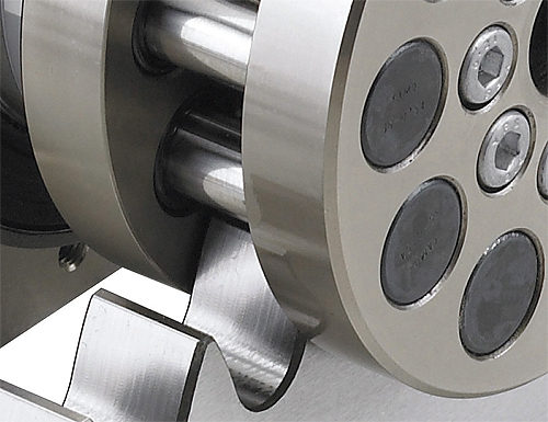
2. Sometime last year or the year prior, I became fascinated with the idea of using roller chain sprockets as gears, by wrapping a length of chain 360deg around a round piece of plate (welded in place) and then having a sprocket mesh with it. Then broadened the concept to include the idea of welding a roller chain down to a flat surface (rack) and having a sprocket drive against it (pinion). Then it seemed more economical (chain isn't cheap) to wrap a short section of chain around a plate (pinion) and have a chain-tooth profiled stationary rack. I discussed all of this on an internet forum, can't remember which one, possibly this one. I probably owe some of these thoughts to other people. It was either presented to me in that discussion, or around that time I discovered of my own accord: Nexen Roller Pinion System.

My idea is either the same as Nexen's, or very similar; I can't tell. Their rack seems to have flat tooth profiles, in much the same way as an involute rack has flat (trapezoidal) profiles. Maybe this is a knock-off of Nexen, but I'm hoping it's an improvement upon it: cycloidal tooth profile. A cycloid is a special kind of curve; not parabolic, not sinusoidal, not Cartesian, not catenary, not circular... none of those. It's its own kind of curve and it has no fixed radius.
Here is the cycloidal trace that would be left by a single roller in an application like the Nexen RPS:

Multiple roller traces:

Multiple roller traces with convergence:

From that last image, it should start to become apparent where the "cycloidal tooth profile" comes from. Here is a picture of the resultant rack:

Here is animation of how it would look if a pinion like the Nexen RPS were to travel over a rack with a cycloidal tooth profile (maybe it already does. but I think/suspect they're using flat tooth profiles):
I'm hopeful that the cycloidal tooth profile, being a perfect match for the cycloidal traces of the rollers, will enable the pinion to not only drive a gantry, but support the gantry as well, in the same way as the square-wheel tricycle. And that's part of the reason I suspect Nexen is using a flat tooth profile; if they were using a cycloidal profile, they should have a demonstration somewhere, of the pinion rolling atop a rack, bearing a load. Either that or my assumptions are incorrect and even with a cycloidal profile there would still be binding... But look at that trike! Its wheels aren't binding!
In any case, even if it can't bear a load, I still think it would be a superior system especially for us DIY types. Do we agree that it could be made in the home (CNC) shop more easily than an involute rack & pinion? Do we agree that it would be zero backlash and more accurate?
I badly want to build and try this, but my CNC is in pieces currently with a long road ahead. If anyone else would like to give it a shot, I would await the results with heavy anticipation. If there are any takers, I could provide a CAD file of the cycloidal rack per the desired dimensions.
EDIT: I forgot to mention. The pinion rollers would be on bearings; probably needle bearings. Maybe the endcap bearings of automotive universal joints would suffice.
I would like to discuss an idea for a (hopefully)-simpler, -more capable, -more accurate, and -more easy-to-DIY linear motion drive that I have conceived (albeit not the first person to think of it). The idea is, for example in the case of a CNC router table or plasma table, to simplify the linear motion strategy by integrating the travelling rollers/wheels and the drive components into a singular assembly, such that the gantry pinion could ride on the fixed rack, and be supported by the rack. Where the typical involute rack & pinion would bind up if the weight of the gantry were placed on the pinion gear and forced down into the rack, this one would (hopefully) not bind up, but would roll smoothly as if it were rolling across a flat surface. I think it would be easy to CNC mill the rack out of flat stock, and likewise easy to cut the pinion; no special tooling or gear hobs required.
I've been tossing this idea around in one form or another for years. I've brainstormed, researched, and discussed it to such lengths that I can't reliably remember the order in which my thoughts were formed, but here's a brief timeline of how I think I got to where I am now.
1. years ago I saw this video or one like it, of an academic physics exercise involving a tricycle with square wheels, rolling on a specifically lumpy surface, whose lumps canceled out the angles of the wheels
It seemed to me that a superior traction could be achieved this way, and could possibly be modified to have absolute traction (zero backlash, zero slip) if modified to meet that need.
2. Sometime last year or the year prior, I became fascinated with the idea of using roller chain sprockets as gears, by wrapping a length of chain 360deg around a round piece of plate (welded in place) and then having a sprocket mesh with it. Then broadened the concept to include the idea of welding a roller chain down to a flat surface (rack) and having a sprocket drive against it (pinion). Then it seemed more economical (chain isn't cheap) to wrap a short section of chain around a plate (pinion) and have a chain-tooth profiled stationary rack. I discussed all of this on an internet forum, can't remember which one, possibly this one. I probably owe some of these thoughts to other people. It was either presented to me in that discussion, or around that time I discovered of my own accord: Nexen Roller Pinion System.
My idea is either the same as Nexen's, or very similar; I can't tell. Their rack seems to have flat tooth profiles, in much the same way as an involute rack has flat (trapezoidal) profiles. Maybe this is a knock-off of Nexen, but I'm hoping it's an improvement upon it: cycloidal tooth profile. A cycloid is a special kind of curve; not parabolic, not sinusoidal, not Cartesian, not catenary, not circular... none of those. It's its own kind of curve and it has no fixed radius.
The cycloid is the curve described by a point on a circle with radius R rolling without slipping on a line (D)
Here is the cycloidal trace that would be left by a single roller in an application like the Nexen RPS:
Multiple roller traces:
Multiple roller traces with convergence:
From that last image, it should start to become apparent where the "cycloidal tooth profile" comes from. Here is a picture of the resultant rack:
Here is animation of how it would look if a pinion like the Nexen RPS were to travel over a rack with a cycloidal tooth profile (maybe it already does. but I think/suspect they're using flat tooth profiles):
I'm hopeful that the cycloidal tooth profile, being a perfect match for the cycloidal traces of the rollers, will enable the pinion to not only drive a gantry, but support the gantry as well, in the same way as the square-wheel tricycle. And that's part of the reason I suspect Nexen is using a flat tooth profile; if they were using a cycloidal profile, they should have a demonstration somewhere, of the pinion rolling atop a rack, bearing a load. Either that or my assumptions are incorrect and even with a cycloidal profile there would still be binding... But look at that trike! Its wheels aren't binding!
In any case, even if it can't bear a load, I still think it would be a superior system especially for us DIY types. Do we agree that it could be made in the home (CNC) shop more easily than an involute rack & pinion? Do we agree that it would be zero backlash and more accurate?
I badly want to build and try this, but my CNC is in pieces currently with a long road ahead. If anyone else would like to give it a shot, I would await the results with heavy anticipation. If there are any takers, I could provide a CAD file of the cycloidal rack per the desired dimensions.
EDIT: I forgot to mention. The pinion rollers would be on bearings; probably needle bearings. Maybe the endcap bearings of automotive universal joints would suffice.
Last edited:


")