Made a few 1/2” x 3-1/2” Fillister head screws for a 20mm Oerlikon cannon and started on a reproduction of a hold down for the same gun. Funny; it’s the smallest kind of gun on the battleship and the only one called a cannon.
-
Welcome back Guest! Did you know you can mentor other members here at H-M? If not, please check out our Relaunch of Hobby Machinist Mentoring Program!
You are using an out of date browser. It may not display this or other websites correctly.
You should upgrade or use an alternative browser.
You should upgrade or use an alternative browser.
POTD- PROJECT OF THE DAY: What Did You Make In Your Shop Today?
- Thread starter wachuko
- Start date
- Joined
- Jul 8, 2017
- Messages
- 95
Made one. have not used it yet. Thanks for the info.One way to get nice turned finishes on difficult materials is to use a shear tool. What is a shear tool?
View attachment 489852
Full story here: https://www.homemadetools.net/forum/shear-tools-lathe-work-59276
- Joined
- Apr 25, 2024
- Messages
- 53
Last night I did the layout for a new PCB for the controller of my proposed cam grinder. It is basically a 2D general purpose controller which with software changes can be made to control many different machines. It is not CNC in the usual sense whereby you feed it G-code for control. Instead it is stand alone controlled by a few external buttons and 1 or 2 MPGs. Controllers for usual CNC are available in their hundreds at low prices so if I was going that route I would simply buy one rather than design my own.
Around 9 hours ago I sent the gerber files (the PCB equivalent of CAD files for engineering drawing) off to JLCPCB and they are already in production. At the time of writing this they are 30% done. I ordered 10 and they are just over 1 euro each. I sometimes make my own PCBs using the milling machine when I am in a hurry, but the quality of professionally made boards is impossible to beat and this time I am not in a rush for them. I marvel at how modern technology permits low volume boards to be made at such low prices.
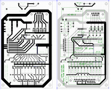
Here is the layout that I made manually using dipTrace freeware. Front of board to the right, rear side to the left. DipTrace produces all the files that are needed by the manufacturer at the click of a mouse button.
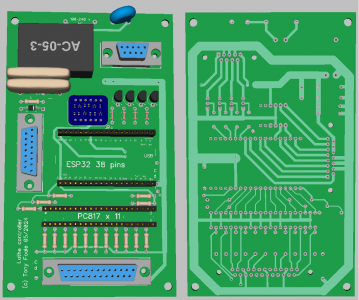
This shows a more realistic view of the finished article.
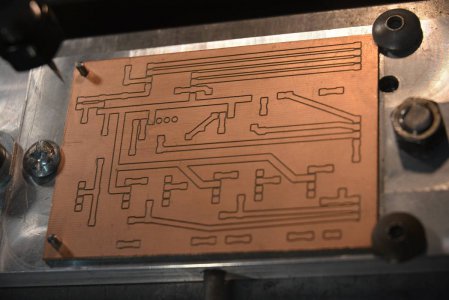
This is an example of an older board done on the mill, for comparison. Also designed in dipTrace software but the milling G-code was then produced in FlatCam software.
Around 9 hours ago I sent the gerber files (the PCB equivalent of CAD files for engineering drawing) off to JLCPCB and they are already in production. At the time of writing this they are 30% done. I ordered 10 and they are just over 1 euro each. I sometimes make my own PCBs using the milling machine when I am in a hurry, but the quality of professionally made boards is impossible to beat and this time I am not in a rush for them. I marvel at how modern technology permits low volume boards to be made at such low prices.
Here is the layout that I made manually using dipTrace freeware. Front of board to the right, rear side to the left. DipTrace produces all the files that are needed by the manufacturer at the click of a mouse button.

This shows a more realistic view of the finished article.

This is an example of an older board done on the mill, for comparison. Also designed in dipTrace software but the milling G-code was then produced in FlatCam software.

- Joined
- Feb 27, 2014
- Messages
- 2,142
Nice work. I have been using Diptrace for years and love it. I often think of making my own boards but as you point out, the price and quality of low volumes of boards from offshore board shops is too good to pass up. I can also get a metal solder stencil at no extra cost making surface mounting a breeze.Here is the layout that I made manually using dipTrace freeware
- Joined
- Apr 25, 2024
- Messages
- 53
Nice work. I have been using Diptrace for years and love it. I often think of making my own boards but as you point out, the price and quality of low volumes of boards from offshore board shops is too good to pass up. I can also get a metal solder stencil at no extra cost making surface mounting a breeze.
I have been thinking that it was time that I got with it in the 21st century and adopted SMC. Could we correspond directly so that I can pick your brains? My email is motochassis@gmail.com
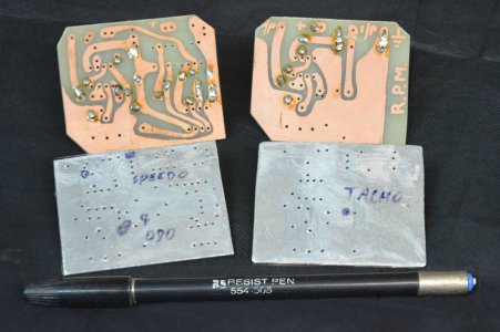
Although I started playing with this 'leccy stuff in 1952 my first PCBs were around 1984. I made aluminium drilling guides. I drilled the holes first and used the holes to guide hand drawing the traces.
Last edited:
- Joined
- Feb 25, 2021
- Messages
- 3,158
Mostly busy with spring work on the hobby farm, but sneaking into the shop ocassionally to work on a few things.
Been pressing my luck (literally) by using a hydraulic press for broaching. Back in March I ordered a Vevor 3T arbor press through Amazon. Wanted the height, if I actually need 3 tons of force I'll go back to the hydraulic press. It arrived with a broken handle, I discussed this with Vevor (through their website portal) and they initially were going to send a new handle but after a few weeks sent a whole new arbor press, saying no need to ship the old one back.
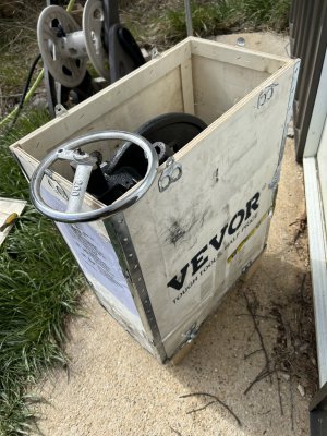
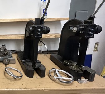
Well, the arbor press, both of them, are pretty sloppy fit. Here's a close-up of the working bits.
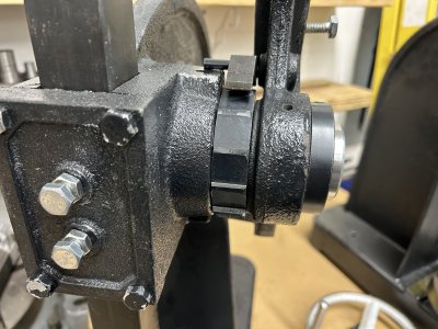
Right to left is a locking ring to hold the press handle, the press handle, a ratchet ring with pawl and a spring pin release, and finally the body of the press. The (broken) wheel goes on the left side of the body. Note the press handle pivots freely on the shaft. The locking ring is held on with a set screw, and the ratchet is held to the shaft with a square key.
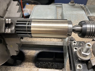
I decided to work on one. Shaft was 2.306" in diameter, the press was bored to about 2.332, the handle around 2.324, the ratchet around 2.334. That made for a press handle that felt like a limp noodle with all the cumulative play in it. Didn't really want to make a new shaft as it has an integral gear cut in it. Decided to put a bronze sleeve on the shaft. Cut the shaft down to 2.00, made a bronze sleeve with the ID of 1.998. Heated the sleeve up nice and hot with a propane torch and slid it on. Turned the sleeve OD to size afterwards:
Bored the handle out, wanted 2.335 but I ran afoul of backlash in the boring head, ended up with 2.342. Decided to live with that.
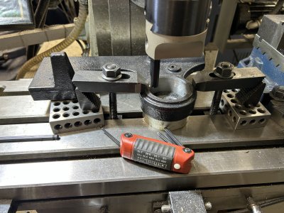
As shipped the ratchet pawl on the handle pivots on an M8 bolt. The bolt is just loose threaded, tightening it down would seize the pawl. Decided to make something a little more elegant.
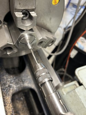
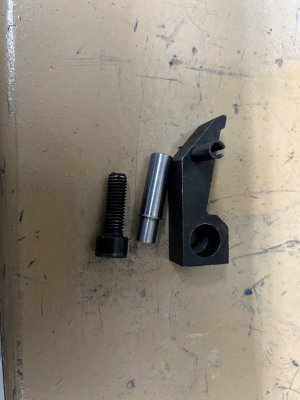
That last pic shows the pawl, the M8 bolt, and the piece of 4130 I turned and pressed into the handle after milling out the previous M8's threads to .375 with an end mill. Did that because the previous hole was a bit off center, plunging an end mill allowed me to center it up. The pressed piece was threaded for a #8 screw to hold bronze cap I made to the size of the M8 head, so it all recessed appropriately. Had to make a small arbor for the bronze cap as my first attempt a few tenths to large for the pawl to pivot freely. I have to believe that the original M8 bolt would be the weak link in pressing. It is only at about a 2:1 advantage from the gear, so 3 tons of press would mean at least 3000 lbs of sideways (shear) force on that bolt through the pawl, ignoring the angles involved. I think the slightly larger 4130 pressed pin should be a bit stronger but still skeptical that it is sufficient for rated capacity.
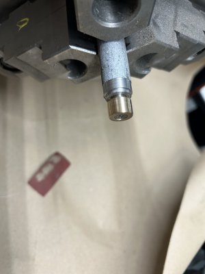
Decided to clean up the ratchet piece a bit so it didn't catch on the body, and used a flat file on that face of the body to take off some of the high spots.
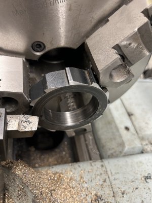
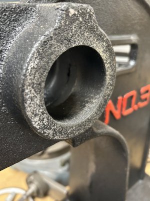
That was partially filed as pictured. Also did some file work on the raised part of the body hub. That raised shoulder acts to disengaged the pawl at the top of handle travel. I cleaned up the inside of the bore with some emory cloth, didn't think it was worth trying to set it up on the mill table to bore it cleaner than the rather rough bored and painted over factory job. To be truthful, I'd already measured that bore ID and turned the bronze OD so I was committed to that size.
Last thing I had to do was mill a new slot for the square key in the shaft through the bronze sleeve. Made the slot extra deep to go through the bronze into the steel, otherwise the press force would be trying to rotate the bronze sleeve on the shaft. With the extra deep slot I had to make up a new no-longer square key (not shown).
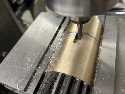
So it is all back together, except I for that pesky broken wheel. I ordered a "boat wheel" off amazon that I'll need to adapt. And I ordered some brass bolts from McMaster to replace the steel bolts that take the play out of the moving press colum. Picture of it all back together? You already saw that above, this is one of those projects where none of the work is obvious by looking.
About $100 worth of parts (mostly bronze) into this, and a lot of time that I enjoyed. Now to decide what to do with the 2nd press.
Been pressing my luck (literally) by using a hydraulic press for broaching. Back in March I ordered a Vevor 3T arbor press through Amazon. Wanted the height, if I actually need 3 tons of force I'll go back to the hydraulic press. It arrived with a broken handle, I discussed this with Vevor (through their website portal) and they initially were going to send a new handle but after a few weeks sent a whole new arbor press, saying no need to ship the old one back.


Well, the arbor press, both of them, are pretty sloppy fit. Here's a close-up of the working bits.

Right to left is a locking ring to hold the press handle, the press handle, a ratchet ring with pawl and a spring pin release, and finally the body of the press. The (broken) wheel goes on the left side of the body. Note the press handle pivots freely on the shaft. The locking ring is held on with a set screw, and the ratchet is held to the shaft with a square key.
I decided to work on one. Shaft was 2.306" in diameter, the press was bored to about 2.332, the handle around 2.324, the ratchet around 2.334. That made for a press handle that felt like a limp noodle with all the cumulative play in it. Didn't really want to make a new shaft as it has an integral gear cut in it. Decided to put a bronze sleeve on the shaft. Cut the shaft down to 2.00, made a bronze sleeve with the ID of 1.998. Heated the sleeve up nice and hot with a propane torch and slid it on. Turned the sleeve OD to size afterwards:

Bored the handle out, wanted 2.335 but I ran afoul of backlash in the boring head, ended up with 2.342. Decided to live with that.

As shipped the ratchet pawl on the handle pivots on an M8 bolt. The bolt is just loose threaded, tightening it down would seize the pawl. Decided to make something a little more elegant.


That last pic shows the pawl, the M8 bolt, and the piece of 4130 I turned and pressed into the handle after milling out the previous M8's threads to .375 with an end mill. Did that because the previous hole was a bit off center, plunging an end mill allowed me to center it up. The pressed piece was threaded for a #8 screw to hold bronze cap I made to the size of the M8 head, so it all recessed appropriately. Had to make a small arbor for the bronze cap as my first attempt a few tenths to large for the pawl to pivot freely. I have to believe that the original M8 bolt would be the weak link in pressing. It is only at about a 2:1 advantage from the gear, so 3 tons of press would mean at least 3000 lbs of sideways (shear) force on that bolt through the pawl, ignoring the angles involved. I think the slightly larger 4130 pressed pin should be a bit stronger but still skeptical that it is sufficient for rated capacity.

Decided to clean up the ratchet piece a bit so it didn't catch on the body, and used a flat file on that face of the body to take off some of the high spots.


That was partially filed as pictured. Also did some file work on the raised part of the body hub. That raised shoulder acts to disengaged the pawl at the top of handle travel. I cleaned up the inside of the bore with some emory cloth, didn't think it was worth trying to set it up on the mill table to bore it cleaner than the rather rough bored and painted over factory job. To be truthful, I'd already measured that bore ID and turned the bronze OD so I was committed to that size.
Last thing I had to do was mill a new slot for the square key in the shaft through the bronze sleeve. Made the slot extra deep to go through the bronze into the steel, otherwise the press force would be trying to rotate the bronze sleeve on the shaft. With the extra deep slot I had to make up a new no-longer square key (not shown).

So it is all back together, except I for that pesky broken wheel. I ordered a "boat wheel" off amazon that I'll need to adapt. And I ordered some brass bolts from McMaster to replace the steel bolts that take the play out of the moving press colum. Picture of it all back together? You already saw that above, this is one of those projects where none of the work is obvious by looking.
About $100 worth of parts (mostly bronze) into this, and a lot of time that I enjoyed. Now to decide what to do with the 2nd press.
Attachments
Last edited:
- Joined
- May 16, 2016
- Messages
- 211
I have been on a major spring cleaning binge as I make room for the mill, and part of that has been trying to get control of my organization. I picked up some reamer storage cases a while back to sort and identify all my misc. reamers, and spent some time last night doing that. I am almost finished, so at least one thing is done


- Joined
- Feb 25, 2021
- Messages
- 3,158
Using Kicad rather than diptrace, but moved to surface mount a couple of years ago for hobby stuff. Pretty trivial with a hot air soldering rework station, a cheap digital microscope, and some high strength reading glasses. I stick to 0805 size for discretes, and try to avoid the fancier (leadless and really fine pitch) surface mount packages. Having JLCPCB doing the soldering/assembly for you is another option but that gets into working with their parts inventory.I have been thinking that it was time that I got with it in the 21st century and adopted SMC. Could we correspond directly so that I can pick your brains? My email is motochassis@gmail.com
Last edited:
- Joined
- Dec 20, 2021
- Messages
- 900
Once you get used to using surface mount parts, it's hard to go back. Having both sides of the board available for components almost doubles the available board space. The next step multiple layers of copper. OshPark.com does 4 layers pretty fast now. Starting to use that more often. I don't think they do blind and buried vias yet, tho. Those really open up possibilities.
For home I stick with 0603 and larger (usually). For $DayJob$, usually nothing smaller than 0402. But BGA packages are getting more common, and those are getting smaller. Worst layout was 1629 components, and 5110 electrical nets. Four 100 pin BGA's, and 1 484 pin FPBGA, in a 4.5 inch circle.
Yeah, I do this for a living so if you have any question, feel free to PM me...


