Installing a Logan QCGB. Logan 9B to 400 adaptation.

LEAD SCREW, Matthew;
Ya gotta talk the talk when ya walk the walk when you make it to the big leagues, dude!? :jester:

Never noticed the lock-down reversing setup on the 400. Wow... there's a place they saved a few beans over the 200.
 
Matthew - Not sure if you have seen this write up or not?
http://lathe.com/ll-group-archive/adapting_a_qc_gearbox.html

I think Scott is talking more 10/11, so the measurements might change ... but the principles should be the same.

Also, look at the dial on the apron you did not buy.

AR1911 - Are those original dials on your lathe??? They look almost large enough to be readable!!
 
Big leagues. Man i just want to stay in the minor leagues. :))

Sometimes i type faster then i think and proof reading is just not one of my strong points.

Thanks for keeping me honest.
 
AR1911 - Are those original dials on your lathe??? They look almost large enough to be readable!!

Yes, those are original. This is a 1962 model. I think the 1957 model 9B I used to own had smaller dials.

- - - Updated - - -

[FONT=century gothic,arial,helvetica]from the Logan page "the Gearbox from the 9"
Lathes are different, although the internal parts are mostly the same (the
Drive Shaft is different, as well as the box itself).[/FONT]"

I thought the 9 - 10- 11-inch lathes all used the LA1201 box?

My 9B and my 11" Powermatic use the same box.

Matt, are you seeing the leadscrew offset mentioned there?
 
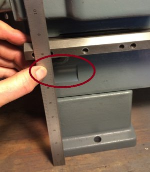
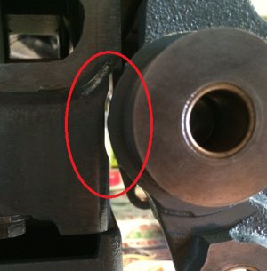
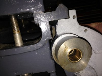
The next part i had to check out was the clearance cut on the 9B bed behind the gear box. What does it clear and do i need to add this?

photosm.jpg photo 2sm.jpg

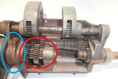
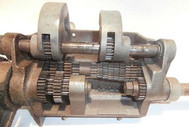
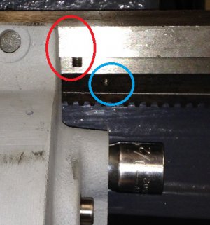
Obviously it clears the gear box. What i could not tell is what part of the gearbox. It would either be the housing or the gears. From the picture below you can see that the casting (Blue circle) sticks out father then the gears. (red circle) To me, this means that the casting is what needs to be cleared, not the gears.

$_573sm2.jpg

Looking at my set-up you can see that the casting clears the bed when the QCGB is aligned to where it mounts on the bed. Given also that i expect the gear box to move out (towards the stud gear) i should be even farther away from hitting the bed.

IMG_0959sm.jpg

My conclusion right now is that i do not need this cut. If i had needed it i would have milled a pocket from the front of the bed with a radius tool instead of trying to stand and clamp the bed to an angle plate to replicate the original cut. I also may have tried a right angle adapter on the mill as i really do like to replicate the original design but for now i think i can put this behind me.

A few post back, Mr. Ed brought up an article by Scott Logan talking about a 11/32" offset of the lead screw to the bed in the front to back orientation. I had read that article but did not attach significance to it as i was using a 9" box.

Right now i have noticed a slight difference in the horizontal plain of the lead screw compared to the bed but not front to back. I will detail the horizontal findings in my next post and will confirm the 11/32" as well. If i find the 11/32" affect me then i may have to re-consider my conclusions in this update. The article is talking more about 10" & 11" units and Scott does state that the 9" box is different. Since we are talking about a 9" to 9" conversion here this may not apply.

Stay tuned.

Matthew

photo 2sm.jpg photosm.jpg $_573sm.jpg IMG_0959sm.jpg $_573sm2.jpg
 
A few post back, Mr. Ed brought up an article by Scott Logan talking about a 11/32" offset of the lead screw to the bed in the front to back orientation. I had read that article but did not attach significance to it as i was using a 9" box.

Right now i have noticed a slight difference in the horizontal plain of the lead screw compared to the bed but not front to back. I will detail the horizontal findings in my next post and will confirm the 11/32" as well. If i find the 11/32" affect me then i may have to re-consider my conclusions in this update. The article is talking more about 10" & 11" units and Scott does state that the 9" box is different. Since we are talking about a 9" to 9" conversion here this may not apply.

Stay tuned.

Matthew
May or may not apply, but keep it in mind. I was thinking of the article another way, it was talking about adapting a gearbox to a non gearbox machine ... albeit 10/11s. What I picked up, was that the non-power aprons (non-QCGB) have the halfnuts at a different elevation than the powered aprons (QCGB).
So the question would be ... did they use the same logic when they designed the 9's? One clue might be to look at the parts diagrams for both versions and see if they had a different support bracket/bearing on the tailstock end of the leadscrew.

Again, I'm not sitting here saying I'm right, and you have the lathe in front of you .... I just like a good puzzle.:think1:
 
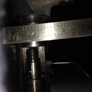
The next item i looked at was the lead screw alignment to the bed. Recall that it appears that the box will mount up close to the end like the 9B and that once shifted for the stud gear the lead screw end support looked ok.

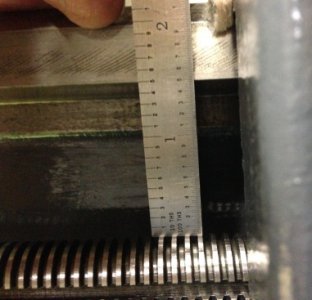
How does the lead screw tram to the bed? Starting from the head stock moving to the tail stock with the saddle near the middle of the bed i looked at the distance from the bottom of the bed to the top of the lead screw. Of course i am assuming that the bottom of the bed is relatively parallel to the top ways and that the lead screw is relatively straight and the same diameter. I think these are reasonable assumptions.

IMG_0977sm.jpg
1.50" at headstock

IMG_0978sm.jpg
1.50" at left side of saddle

IMG_0979sm.jpg
1.45" at right side of saddle

IMG_0981sm.jpg
1.40" at tail stock.

Note that the half nut nor the rack drive gear were engaged. I rise .10" from the head stock to the tail stock. Probably not good.

I also need to check out the front to back to the bed as well. I have yet to do that. I will re-take the measurements above at the same time to make sure i understand what i need to do in both axis.

Matthew

IMG_0977sm.jpg IMG_0978sm.jpg IMG_0979sm.jpg IMG_0981sm.jpg
 
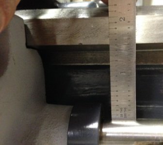
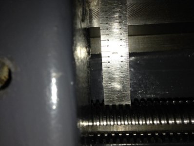
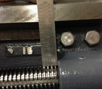
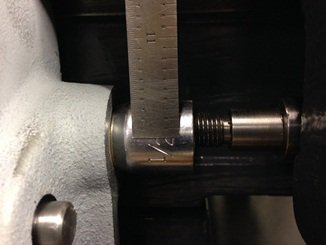
And now for the other direction. How well does the lead screw align to the bed front to back.

I again lined up the QCGB and shimed it in place with the lead screw installed. This time i shifted the gear box like i expect to do when i get the stud gear info. Interesting that the end of the lead screw once the box was shifted aligned perfectly with the end of the support. Hmm.....

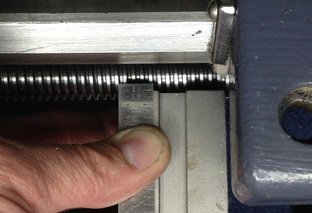
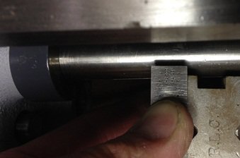
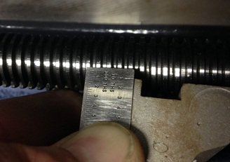
These pictures were hard to get. What i did was align the scale to the front edge of the bed which is directly over the lead screw. I sighted down the side of the bed's front edge and aligned the scale to that sighting. Once i aligned the scale, my "V" block, which was against the lead screw and also aligned parallel to the bed edge gave me the measurement. I then backed off to take a decent picture of the measurement. Otherwise i could not focus on the edge and the scale at the same time.
IMG_0994sm.jpg
Head stock is about .130"

IMG_0996sm.jpg
Left side of saddle with saddle to the right is about .110"
IMG_0995sm.jpg
Tail stock is about .100"

I would say that i do not have the 11/32" issue with this system. I will reserve judgement though until i get my half nut installed. I think the best way to figure out my alignment is going to be with the half nut engaged and more or less letting it set the lead screw where it should be. It looks though like i am not too far off.

Can anyone measure for me your stud gear shaft? Or the distance the stud gear stands off from the reversing lever mount surface and some good pictures of the spacer? I am sure the design is the same, just farther out. I suspect i need to make a shaft.

:anyone:


The next topic will be the height of the bed. I am going to double post here as i am in catch-up mode right now with the projects documentation.

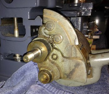
When i mounted the gear box before i took it apart i thought there was no way the selector levers would clear the deck. So how high does the bed need to be?
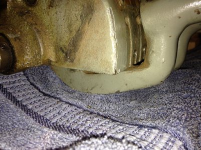
IMG_0848sm.jpg IMG_0849sm.jpg
My gear box as you can see just barley clears the table. (Wish i had removed the towel for the picture.)
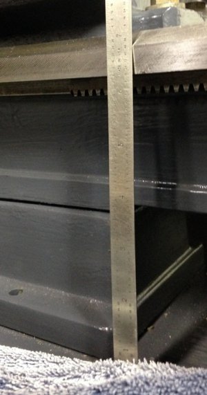
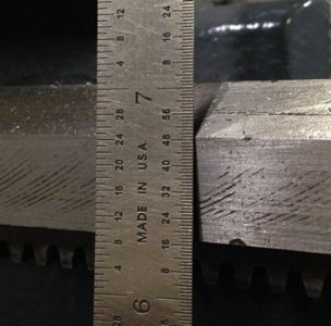
IMG_0954sm.jpg IMG_0955sm.jpg
Measuring my Logan 400 the distance from the table to the "V" is ~6.8". I am measuring to the front face transition to the "V" as that is the comparable measurement i have.
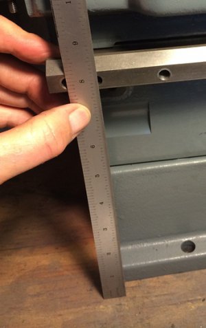

photosm2.jpg
The same measurement on a 9B is about 8.2"


The logan 400 is about 1.4" lower than the 9B. I do not know if the difference is in the risers or the bed. Seems like they would have re-used the bed casting but i do not have any supporting data except that i need to raise up the Logan 400.

I will do this by adding 1.5" square risers between the table and the lathe.

Matthew

IMG_0994sm.jpg IMG_0995sm.jpg IMG_0996sm.jpg IMG_0848sm.jpg IMG_0849sm.jpg IMG_0954sm.jpg IMG_0955sm.jpg photosm2.jpg
 
If you look at the photos you posted of you 400 and my 9B, it's plain the difference is in the risers. I'd bet the bed is the same.
 
Lead Screw
Did some more alignment work on the lead screw last night now that the half nut is installed. I supported the lead screw with the half nut and then moved the saddle to the rear to see how well the lead screw naturally would align to the end support. It aligned perfectly but i expected that. I then did the same to the gear box. Things did not line up so nice. ( note that the half nut was near the part i wanted to test fit and the other end of the screw was supported by either the end support or gear box. My theory is that the half nut would align things close enough to tell what was going on.)

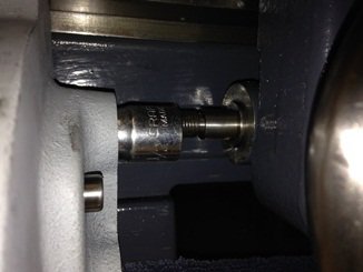
Honestly it was hard to get a good picture or measurement. I can say that the box needs to be milled to align to the shaft. I think i will have to take baby steps when doing the work. Here are a few pictures but take the measurements with a grain of salt.

IMG_1011sm.jpg
From the front. (i placed a socket into the bore to have another diameter to align to.)

IMG_1014sm.jpg
from the bottom.

What bothered me is that i did this twice and both results were not the same. Not even close. Above are the closer of the two trials.

IMG_1005sm.jpg
this was the first trial. You can see the shaft is farther off. I am not sure what to do with this right now.


Longitudinal rack.
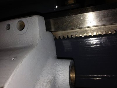
What is going on. In post #25 i hinted of a problem there. Now that i understand more where the box might end up i can look at what is needed here.

The rack for sure interferes. This picture is with the box aligned to the left side of the bed.

IMG_0951sm.jpg

Here is the box aligned where i think it will go. I then placed a rack mount screw in the farthest left hole in the bed (red circle) and then aligned the rack against the box. By rotating the rack you can see how far off the screw is to the hole. (blue circle)

I need to remove about 5/8" from the rack and it will mount. Easy mod.

IMG_1018sm2.jpg

New part
IMG_0997sm.jpg

IMG_1001sm.jpg

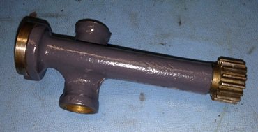
I think it is from a 10" logan but honestly the seller was not sure. There are two styles out there. This one seamed to have the right spacing between the gear and mount screw. Could not tell how to get it apart to clean it but it was in great shape. Re-painted it and installed it.

How is it made?

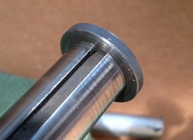
My gear selector shaft is shot. have to make a new one. I figure the end cap is plug welded. i am looking to internally thread it or similar.

IMG_0989sm.jpg

Matthew
IMG_0951sm.jpg IMG_1011sm.jpg IMG_1014sm.jpg IMG_1005sm.jpg IMG_0997sm.jpg IMG_1001sm.jpg IMG_1018sm2.jpg IMG_0989sm.jpg
 
Back
Top