- Joined
- Feb 5, 2015
- Messages
- 662
This post was inspired by a similar thread in which one of our members made a clever mounting system for an ER-40 collet chuck. I did this project several years ago so this is just a recap of the procedure.
I have an odd little lathe, an Emco "Compact 8", an economy model of the "Maximat 11", both made in Austria. I bought the used machine some thirty years ago and could have obtained a SB heavy ten in good condition for the same price. At the time, however, most of my work was non-ferrous and less than an inch diameter so the little Emco seemed like a natural with its high spindle speed and short, stout aspect ratio. I might have been more patient had I thought about my future needs: larger work and ferrous material.
Over the years, the lathe has worked well although there have been occasions where I wished for a better drive system than vee-belts and a longer bed than 18 inches between centers provides. Another thing that would have been useful is a large-capacity collet system. These are not available for the machine because of the headstock spindle taper and small bore.
This hasn't been troublesome because I rarely make more than one or two of anything and the parts don't normally need to be processed for other operations (requiring them to be turned around in the chuck, for example). The original 3-jaw and two 4-jaw chucks have been adequate for my purposes. Nevertheless, I occasionally wanted something with better precision than the 3-jaw and that could be set up quicker than a 4-jaw which prompted me to buy the 6-jaw chuck that I negatively reviewed here:
http://hobby-machinist.com/index.php?topic=415.0
After I acquired ER-40 collets for my horizontal mill it was natural to consider using ER-40 collets in the spindle (as well as in the tailstock) of the lathe. I have seen ER-32 headstock collet chucks for small lathes, available here in the U.S. and I've seen ER-40 headstock collet chucks available from several British websites.
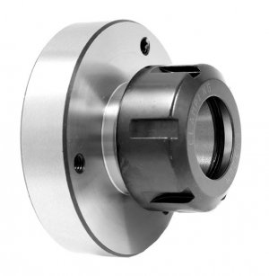
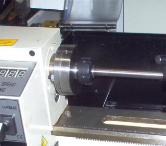
In fact these devices are perfectly sized for my lathe, they are 100 millimeter diameter with 72 millimeter registration diameter - the same mount as my Emco. Shown below is a photo that I lifted from one of the U.K. suppliers, the collet chuck appears to be mounted on a ten or twelve inch machine. These chucks are reasonably priced in the U.K. but the sites where the devices are listed don't indicate an option for shipping to the U.S.
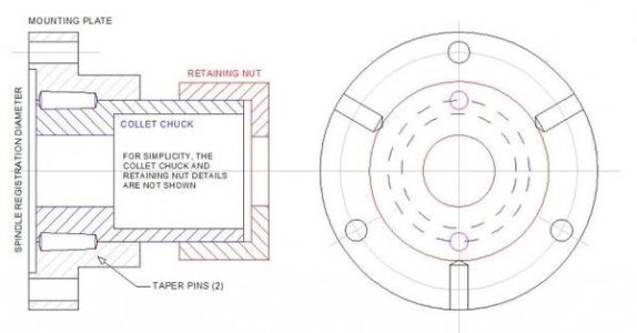
A possibility would be to buy an inexpensive straight-shank ER-40 collet chuck, cut off the shank and adapt the collet chuck to my spindle. That is where my thinking had evolved, in fact I had located the part from which the adapted collet chuck could be made but not ordered it. This is what I had in mind:
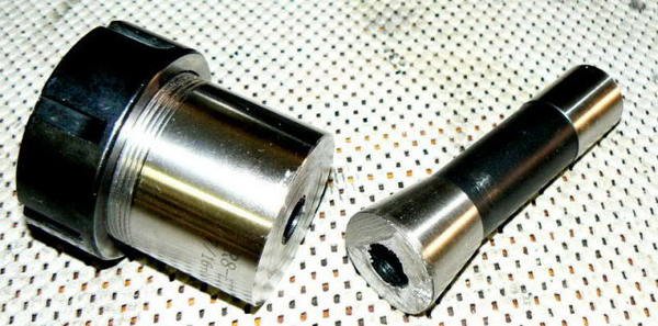
So here's where this long-winded story finally connects the dots: when I realized that the runout of the R-8/ER-40 collet chuck purchased for the vertical mill made it unusable, my immediate reaction was to place it in the bandsaw and hack off the R-8 arbor, LOL.
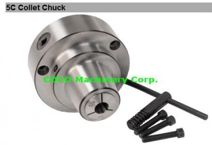
One of the reasons that 5C collet chucks for small lathes have never attracted me is the overhang and relatively flexible construction (the gearing mechanism required to thread the collet is in front of the spindle mount - the most sensitive location). A number of these devices are available, ranging in price from $140 to $400 (probably all made in the same factory). Here's an example of one, this one happens to come from CDCO, the distributor from whom I ordered the not-so-good R-8/ER-40 collet chuck:
The 5C lathe collet system is probably the most widely used for general workholding in medium-size lathes. It can accommodate many odd workpiece configurations, can be loaded/unloaded without stopping the spindle in some machines, doesn't require large clamping torque and economies of scale makes the collets inexpensive.
Unhappily, small lathes can't accommodate 5C collets except in the mechanism shown above which eliminates almost all of the advantages of 5C collets except their availability and adds a few disadvantages.
A small 4-jaw chuck (or a 3-jaw chuck with jaws shimmed for concentricity) is probably preferable to lengthier overhang, loss of rigidity and loss of carriage travel. (Doesn't sound like much, LOL, but when using a machine with an envelope of 8 x 18, a few inches can be significant.) The ER-40 collet chuck also has overhang but doesn't exceed the overhang of the 3-jaw chuck and is more rigid than the 5C mechanisms because of locking tapers at both ends of the collet rather than a single taper like a 5C.
After retirement, usage of my metalworking machinery changed from small, nonferrous workpieces required by my previous professional needs to larger (mostly steel) work. As a consequence, a few items in the shop also needed to change. The little 115 VAC MIG welder had to be upgraded to a 230 VAC Miller 211 and a horizontal mill was added because the small 8 x 30 vertical didn't work steel as efficiently as I'd like.
I added two more drill presses; with three drill presses, I can keep sanding flap-wheels, countersinks for deburring, wire wheels and so forth mounted in one or two drill presses while keeping one free for drilling. (One of the drill presses is a floor model and is configured with the vise mounted sideways for drilling the ends of long workpieces.)
So maybe the old 3-jaw chuck on the lathe could still be the primary workholder but a collet system would be convenient provided that it can be installed/removed quickly and didn't cost much. I know, I know - the solution is to add another, larger lathe so that one machine can always be set up with collets and one with a chuck.
And that's a sensible solution that I eventually followed by adding a 1944 Sheldon EXL-56B that is permanently set up with a 4-jaw chuck. Here’s a photo after I made a backplate for the 4-jaw but before I cleaned up the machine.
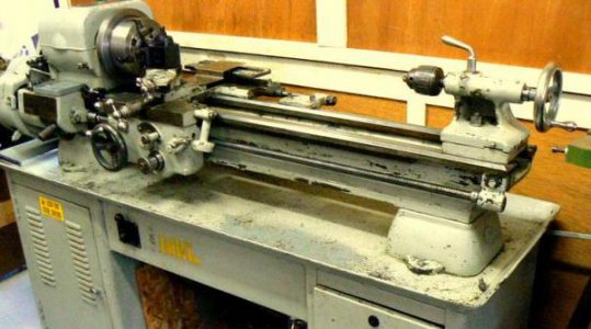
In addition to unavailability, the reason for making my own system (actually adapting an existing system) was to overcome alignment problems that are typical in inexpensive workholders. There are two obvious sources of errors: concentricity (or lack) and angular axial error.
The first is obvious but the second is sometimes overlooked by many proponents of 4-jaw chucks. It is easy enough to dial in the 4-jaw chuck to a required concentricity at ONE point on the workpiece but angular axial error guarantees that concentricity won't exist at another point on the workpiece (this may not be important, of course).
My plan was to permanently attach the ER-40 collet chuck to a back plate, allowing excess stock for finish machining to fit my lathe spindle interface. The finish work was to be performed with the collet chuck secured on a mandrel between centers (verifiably aligned with the lathe spindle).
With the collet chuck clamped on a trued shaft, the mounting plate could be faced and the locating recess bored. It was my belief that this method would provide good accuracy given the equipment available to me. The end result was obviously going to be affected by errors introduced at each stage of the process so patience and careful planning would be rewarded.
I needed a piece of steel plate from which I could machine a holder for the ER-40 collet chuck, the finish dimensions of the mounting plate would be about four inches diameter x 1-3/4 inches thick. I didn't have anything like that in my modest stock of ferrous materials and I didn't want to use aluminum.
"Behind the redwood curtain" (as local residents describe our environment) we have no metal suppliers - they are many hours drive from us so everything that isn't stocked at the hardware store must be shipped in. Checking the usual internet sources, I was astounded (as always) by the prices these people want for their treasures - not to mention the shipping cost. The best quote I received was $32.51 + shipping for a steel dropout adequate to make a back plate.
I had an idea that I could do better and took another look at the importer's website from which I had purchased the (unacceptable) R-8/ER-40 collet chuck and found that I could buy a semi-finished cast-iron backplate for a four-inch chuck for $29 plus shipping. Not only was this cheaper than the steel blank but the rough machining was done. This didn't include shipping, however, which added another $10.
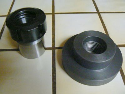
If another tool is needed and can be obtained from the same distributor, then it can usually be included without adding to shipping cost. In this case, I needed some 1/8 shank carbide burrs for a Dremel tool - they are light and the shipping fee didn't increase from the addition. Here's the backplate along with the ER-40 collet chuck (cleaned up in the lathe after sawing off the R-8 shank):
A decision needed to be made regarding the means of securing the ER-40 collet chuck to the mounting plate. The interface must be able to withstand the amount of torque that a heavy depth of cut causes without impairing accuracy. Brazing would be an obvious choice except that the modest heat-treated qualities of the ER-40 collet chuck would be lost.
Brazing would anneal the internal taper of the chuck, limiting lifetime of the device. Welding the cast-iron mounting plate to the heat-treated steel collet chuck wasn't even considered. I chose to shrink fit the two parts together.
Shrink fits are a good way to precisely and permanently secure two parts but there are a few precautions that must be observed. The desirable result is an immovable joint that doesn't exceed the allowable material stress of the weakest part (which might result in either cracking the cast material or causing permanent plastic deformation that would slip under load or deflect). (As in any strength problem, the elastic limit and ultimate strength must not be exceeded and this is going to limit the interference of the fit.)
If the interference of the shrink fit doesn't appear adequate to carry the torque of the assembly, then supplementary means can be provided. It's easy enough to add a couple of taper pins, as shown in the original drawing.
The imported mounting plate appears to be cast-iron but I have no way of knowing what alloy or what impurities might exist in the part. I have to assume that this will be the weakest part of the assembly, rather than the semi-hard collet chuck.
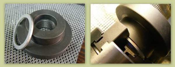
After calculating the amount of interference between the two parts (.0022), the cast-iron back plate can be bored to the correct dimension. There's no need for the bore to be precisely concentric with the features of the back plate - it's a casting - so it can be held in a 3-jaw chuck, no problem. Since the design requires that the bore go completely through the back plate, we need to make sure that there's no possibility for the boring bar to strike the hardened jaws of the chuck. A thin slice of aluminum tubing made a good seat for the back plate, fitting between workpiece and chuck jaws.
The 4-way toolpost was replaced with a boring bar holder and a 1/2 inch shank carbide boring bar installed in the holder. The length of the bar should be just long enough to make the operation - but not longer - because of the flexibility of the setup. The back plate was first roughed by hand-feeding the carriage. I like to do this with tools that aren't very sharp, like this imported boring tool, so that I can feel the resistance of the work. Small lathes don't have a separate feed mechanism, they use the leadscrew for feeding and there's no need to stress it unreasonably.
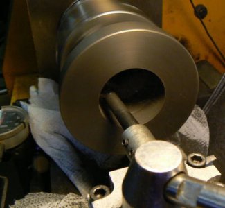
A couple of comments regarding the above photo are addressed to those who are newcomers to this craft. The first is that cast iron needs to be turned dry and the second is that particles of this material are abrasive and can damage precision surfaces. So before turning this material, wipe down the lathe to remove coolant and lubricants which will cause the chips/debris (from the machining operation) to "stick" to the machine. Although there's no way to fully protect the machine, cover what can be covered with paper towels, toilet paper or other disposable material. (Don't use rags - the temptation might be to wash and re-use them and, like abrasive grit, harmful particles will not be completely removed.) If you can, rig a shop vac hose near the cutting tool, or hold it there manually.
After rough-boring within .020 of finish diameter, I stopped the lathe, cleaned up and then "touched up" the boring cutter edges with a diamond lap. (This can be done without removing the tool from the lathe if you are careful.) Carriage feed is recommended for the remaining operations, rather than hand-feeding the carriage.
For finish boring the same amount of resistance to the tool during each pass is required to obtain consistent results. I planned on making three passes, using the same depth of cut for each pass and keeping the cutting conditions as consistent as I could (and not leaning any part of my body on the lathe while the carriage is feeding, LOL). I made two passes of about .006, measured one last time and then made the final pass.
Precision bore measurements have always been a pain for me because I don't have good tools. For the most part, telescoping gauges and good vernier (not dial) calipers have been good enough for my work but then I don't usually work to "tenths" precision as in fitting ABEC-7 bearings, LOL ! So when I DO have to work to this level of accuracy, I practice to get the "feel" of gauge and micrometer, using a known bore as a standard (within the range of the same telescoping gauge to be used for the actual workpiece).
The reason for making THREE passes is so that the consistency of the boring operation (and my measurement technique) could be assured. If the first two passes remove identical amounts of material then I could be fairly certain that the finish pass would do the same … providing that the depth of cut is similar and that no other variables have been changed (don't change the feed, the speed, add coolant, "touch-up" the cutting edge - nothin' - in other words).
A post that discusses some of the contributions to precision boring can be found below and it's well worth reading (although it is directly related to a machine that many of us will probably never see). The methods that I used to produce the accurate shrink-fit were the direct result of reading that post and "listening" to those who work within these tolerance limits routinely:
http://hobby-machinist.com/index.php?topic=324.0
It's easier to produce a precise male diameter than the mating female diameter, in my opinion. Cutting tools are usually easier to sharpen and making the measurements are simpler for me. Precision bore measurement instrumentation that is accurate and repeatable will cost $$$ when "tenths" tolerances are required ! Luckily everything worked out for me so I could progress to the actual shrinking operation.
After cleaning the two parts to be shrunk together, I put the ER-40 collet chuck in the back of the freezer. I placed the back plate in the kitchen oven, adjusted to its highest temperature setting. Near the oven on the countertop, I placed a scrap of plywood on which to rest the heated parts in addition to the brass hammer and channel-lock pliers. Now we need to allow the parts to reach temperature which will take about an hour.
So, back out to the shop - use that hour of waiting to carefully clean the lathe and tooling. First, remove and discard the paper towels containing abrasive cast-iron material then use a shop vacuum to remove as much of the remaining debris as possible. When you are satisfied that there's no residue, wipe the machine down with paper towels or toilet paper, folding the paper after each wipe so that dirt/grit aren't transferred to another surface.
Repeat until the tissue paper remains clean in appearance when wiped on any ground surface or moving part. Now follow the same procedure around every oil fitting on the machine - there's no point cleaning the ways if cast-iron grit gets re-introduced through lubrication ports ! After you're done, which should take about an hour, it's time to assemble the parts that are in the freezer and oven so here we go :
The collet chuck was first removed from the freezer with welding gloves, held briefly while the other hand carefully removed the back plate with the channel-lock pliers. After placing the HOT piece on the plywood scrap, the collet holder easily dropped into the back plate. The brass hammer wasn't needed and the two parts shrunk together within a minute. They were allowed to cool slowly for several hours before handling.
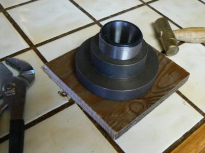
The assembly needed to be transferred to the vertical mill for a few details before boring the registration diameter that aligns it with the lathe spindle. Recall that the collet holder was sawed from an R-8 arbor so the internal details of the holder intercept the drawbar threads that were tapped through the R-8 shank. The first requirement was clearing out the drawbar threads so that stock may be fed through the collet chuck.
After clamping the collet chuck in place on the mill table, a short length of ground shafting was secured in a collet so that the part could be dialed in to establish a reference location. After locking the "X" and "Y" axis, I plunged a one inch end mill about 1/2 deep at the end of the chuck pocket; the purpose was to give a one inch drill a good, accurate start. (When facing off the saw cut end, I had noticed that the 7/16 - 20 drawbar threads at the bottom of the collet chuck weren't very concentric with the body.)
As a matter of interest, I'd estimate that the collet chuck was somewhere in the mid-forties of the Rockwell "C" scale - not real difficult to work but a situation where one might feel more comfortable with carbide tools and cobalt drills.
Why not just plunge the end mill through the part ? Because if it dulled, I have no means to accurately re-sharpen it. The one inch twist drill, on the other hand, is fairly easy to sharpen free-hand on a grinder. The twist drill followed the end mill operation, providing the desired clearance diameter through the collet chuck.
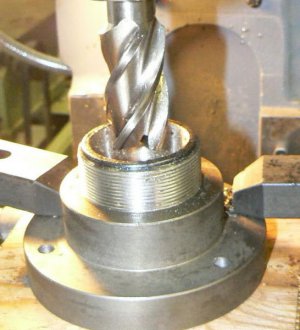
After confirming with an indicator that the part was still centered, hole offset locations were dialed off and the three spindle mounting holes were drilled and tapped for the 8 mm spindle mounting screws.
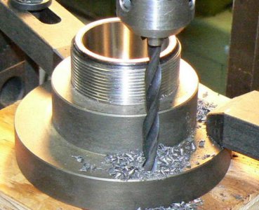
ER-40 collet chucks require a considerable amount of tightening torque for large diameter workpieces so several 3/8 holes were drilled around the perimeter of the backing plate, as shown in the original drawing. These are for inserting a temporary retaining bar ("tommy bar") to hold the spindle stationary while tightening the collet retaining nut. The holes are located midway between the spindle mounting holes and were drilled with the collet chuck held upright in the milling vice.
When angular accuracy less than one degree is not required, a protractor head with spirit level can be useful for setting up a job like this one. The protractor head is first calibrated by centering the bubble while the head is firmly held on the bottom of the milling vise. The protractor is now perpendicular to the vertical spindle when it is set to "0" degrees (within its accuracy limits).
Slipping two snug-fitting pins through two of the holes in the workpiece provides a convenient "rest" for the protractor head. The milling vise is tightened just enough to prevent the workpiece from moving … the workpiece is then carefully rotated until the protractor indicates "level" and then the vise is tightened. (The two pins are visible protruding from the front of the workpiece.)
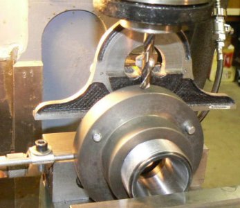
After drilling the perimeter holes, the vertical mill was vacuumed and carefully cleaned to remove cast-iron chips and debris. There were a lot more cracks and crevasses for the chips to creep into so it took more time to clean up - especially since I'd neglected to place paper towels around the workpiece. (I'm normally not this forgetful when it comes to minimizing dirty work, LOL.)
The final operations were important because they establish concentricity and axial alignment of the collet system. Recognizing that there were limitations to the practical accuracy achievable from this inexpensive system, I still spent a few moments going over the lathe, making sure that slides were snug and that spindle bearings were still properly adjusted. There were already built-in inaccuracies to the collet system but I didn't want to add to them, LOL.
Next step was to make a mandrel on which the collet chuck could be affixed while boring the registration diameter and facing the surface that mates with the spindle. I had some one inch ground drill rod so I cut off a 14 inch length and temporarily chucked it in the lathe. With a dead center installed in the tailstock, I placed the tailstock in a position to support the mandrel and marked that location.
The mandrel blank was removed and a shop made measurement tool was installed in the 3-jaw chuck. This is a tool that finds occasional use, it's a .0005 increment DTI mounted at a slight angle to a 1/2 shaft about 18 inches long. (One of those "temporary" tools, made in a few minutes, that manage to avoid being deposited in the scrap bin.) The purpose was/is to indicate tailstock tooling true to the spindle axis.
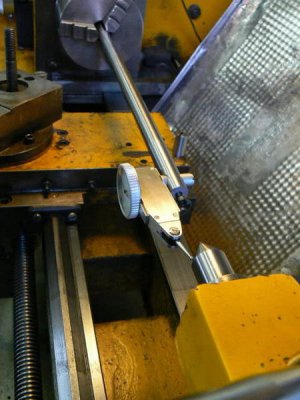
The indicator tool was used to align the dead center when it was located at the position I'd previously marked, it was about .001 off - not too bad for a small and well-used lathe. I tweaked the adjusting screws and then removed the DTI tool. (FWIW, some may wonder about indicating top-to-bottom alignment when deflection from the weight of the assembly is considered. For the tool described above, the maximum deflection is .0002, fully extended. The deflection can be ignored when the tool extension is less than ten inches since it is less than the .0005 DTI can measure.)
Removing the dead center to provide clearance, the mandrel was chucked again. After checking concentricity (about .020 runout 12 inches from the chuck) I center-drilled a 1/4 center hole in the end of the mandrel. I did this at about 120 RPM to prevent "whipping" of the mandrel during the center-drilling process. Replacing the center drill with the dead center, lubricating the center and "snugging" it against the mandrel, I turned a four inch length of the mandrel true with the spindle axis. Measuring both ends of the turned diameter showed .0004 taper so I carefully, very carefully tweaked the tailstock adjusters .0002 until there was no measurable taper then turned the diameter to 15/16 (to suit the next smaller diameter collet in the ER-40 series).
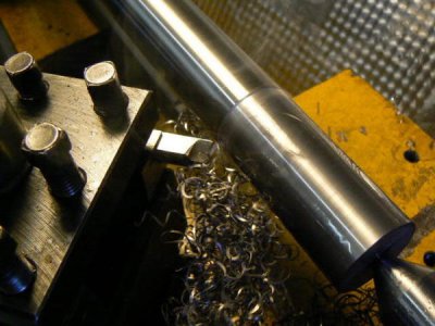
I measured the mandrel once more to confirm that it was not tapered and then backed away the tailstock so that the collet chuck assembly could be installed over the mandrel and secured. Why do I want to bore the registration diameter at the tailstock rather than the headstock, as would be normal ?
Because this is an older machine and almost all work has been short pieces near the headstock. Boring at the tailstock end means that the carriage is located on an unworn part of the ways. Nit-picky, of course but really an experiment … one of these days I might really need the precision that turning near the tailstock could provide.
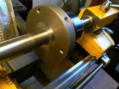
Moving the tailstock forward, the dead center was lubricated again, engaged with the mandrel and tightened in place. The tailstock ram was rotated slightly to snug the center into the mandrel. A marker diameter, about .100 smaller than the finish diameter, was first established before commencing the rough boring. In the photo, the tool is removing material near the mandrel then progressing outward toward the marker diameter.
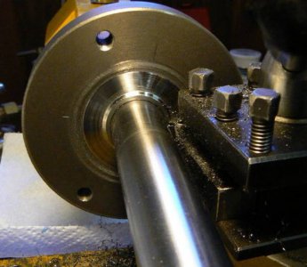
The area near the mandrel didn't receive much attention as to depth or finish and that will be corrected later … here is the finished registration diameter after boring and before cleaning up the area near the mandrel. As noted several times earlier, no coolant is used and paper towels are placed to collect as much of the cast-iron debris as is possible.
The set-up was broken down, workpiece removed from the mandrel and mandrel removed from the chuck. A one inch diameter pin was installed in the 3-jaw chuck and the ER-40 collet chuck with one inch collet was installed over the pin and securely tightened. The area of the registration diameter near the mandrel that was previously inaccessible could now be faced.
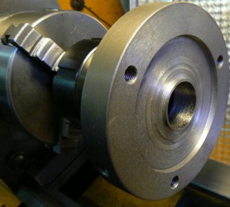
And now, we're done.
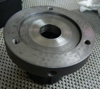
Summary And Afterthoughts
It had been a long time since I'd last removed the 3-jaw chuck from the lathe spindle and I'd forgotten what a huge pain in the neck it is to remove and install. Here's a photo that illustrates the problem:
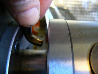
There's about 3/4 of an inch clearance between the spindle face and the bearing cap at the front of the headstock. Spindle workholders are held to the spindle face by three 8 mm socket head cap screws through counterbored holes on the rear of the spindle face. There is barely enough room to get a finger in there and as you can see, the hex key had to be ground down in order to insert it.
I didn't even bother to mount the new collet chuck, I knew that I wouldn't be able to live with this ten-minute exercise in frustration every time I needed to change a chuck, LOL. I was tired and I made a poor decision: I decided to use hardened clamping studs and flanged nuts from the tee-slots on my rotary table to mount the ER-40 collet chuck. I put the chuck back in the vertical mill and plunged an end mill through the three tapped mounting holes to provide clearance for the studs.
As I removed the part from the milling vise, I realized that I had blundered. I could have simply permanently installed three studs in the tapped holes, slipped the studs through the spindle mounting holes and made three large diameter flanged hex nuts to secure the collet chuck. Hex nuts would be easy to tighten with an open end wrench at the rear of the spindle face, rather than messing around with the ground-down hex key ! The three jaw chuck and the four jaw chucks could be similarly equipped with studs.
Oh well … so the collet chuck is now mounted with the studs and flanged nuts from the rotary table. It works fine, actually, but I'll probably modify the mounting eventually. The most convenient means would be fixed studs through the spindle face but that's not going to happen - the entire headstock would have to be disassembled, LOL, to gain access to the rear of the spindle face.
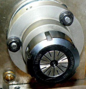
The ER-40 system is not ideal for a lathe, it is meant as a toolholding system rather than a workholding system. It requires more torque to tighten than a 5-C collet and more time to remove and install parts because the collet is not self-releasing (the retaining nut must be backed off several turns to release the collet grip).
Despite these shortcomings, it is a good system for my situation, allowing diameters up to 1 inch to be held and diameters up to 3/4 inch to be passed through the spindle. I'm retired and I rarely make more than three or four of anything so the extra time required to load/unload the collets doesn't trouble me.
The overall cost of the collet chuck, neglecting my time, was less than $50 (and I already had two sets of ER-40 collets that are used in other machines). The runout of this 3/8 drill rod, one inch from the face of the collet, is .0006 and at three and one-half inches from the face of the collet is .0018. (I doubt that I can improve on this performance since the collet chuck itself is specified at .0008 inches runout at 1.6 inches from the collet face.)
At present, I've never removed the collet system from the little EMCO and never removed the 4-jaw chuck from the Sheldon. Between the two workholding systems, I've managed to muddle through any situation that I've encountered in the past few years
I have an odd little lathe, an Emco "Compact 8", an economy model of the "Maximat 11", both made in Austria. I bought the used machine some thirty years ago and could have obtained a SB heavy ten in good condition for the same price. At the time, however, most of my work was non-ferrous and less than an inch diameter so the little Emco seemed like a natural with its high spindle speed and short, stout aspect ratio. I might have been more patient had I thought about my future needs: larger work and ferrous material.
Over the years, the lathe has worked well although there have been occasions where I wished for a better drive system than vee-belts and a longer bed than 18 inches between centers provides. Another thing that would have been useful is a large-capacity collet system. These are not available for the machine because of the headstock spindle taper and small bore.
This hasn't been troublesome because I rarely make more than one or two of anything and the parts don't normally need to be processed for other operations (requiring them to be turned around in the chuck, for example). The original 3-jaw and two 4-jaw chucks have been adequate for my purposes. Nevertheless, I occasionally wanted something with better precision than the 3-jaw and that could be set up quicker than a 4-jaw which prompted me to buy the 6-jaw chuck that I negatively reviewed here:
http://hobby-machinist.com/index.php?topic=415.0
After I acquired ER-40 collets for my horizontal mill it was natural to consider using ER-40 collets in the spindle (as well as in the tailstock) of the lathe. I have seen ER-32 headstock collet chucks for small lathes, available here in the U.S. and I've seen ER-40 headstock collet chucks available from several British websites.
In fact these devices are perfectly sized for my lathe, they are 100 millimeter diameter with 72 millimeter registration diameter - the same mount as my Emco. Shown below is a photo that I lifted from one of the U.K. suppliers, the collet chuck appears to be mounted on a ten or twelve inch machine. These chucks are reasonably priced in the U.K. but the sites where the devices are listed don't indicate an option for shipping to the U.S.

A possibility would be to buy an inexpensive straight-shank ER-40 collet chuck, cut off the shank and adapt the collet chuck to my spindle. That is where my thinking had evolved, in fact I had located the part from which the adapted collet chuck could be made but not ordered it. This is what I had in mind:

So here's where this long-winded story finally connects the dots: when I realized that the runout of the R-8/ER-40 collet chuck purchased for the vertical mill made it unusable, my immediate reaction was to place it in the bandsaw and hack off the R-8 arbor, LOL.

One of the reasons that 5C collet chucks for small lathes have never attracted me is the overhang and relatively flexible construction (the gearing mechanism required to thread the collet is in front of the spindle mount - the most sensitive location). A number of these devices are available, ranging in price from $140 to $400 (probably all made in the same factory). Here's an example of one, this one happens to come from CDCO, the distributor from whom I ordered the not-so-good R-8/ER-40 collet chuck:

The 5C lathe collet system is probably the most widely used for general workholding in medium-size lathes. It can accommodate many odd workpiece configurations, can be loaded/unloaded without stopping the spindle in some machines, doesn't require large clamping torque and economies of scale makes the collets inexpensive.
Unhappily, small lathes can't accommodate 5C collets except in the mechanism shown above which eliminates almost all of the advantages of 5C collets except their availability and adds a few disadvantages.
A small 4-jaw chuck (or a 3-jaw chuck with jaws shimmed for concentricity) is probably preferable to lengthier overhang, loss of rigidity and loss of carriage travel. (Doesn't sound like much, LOL, but when using a machine with an envelope of 8 x 18, a few inches can be significant.) The ER-40 collet chuck also has overhang but doesn't exceed the overhang of the 3-jaw chuck and is more rigid than the 5C mechanisms because of locking tapers at both ends of the collet rather than a single taper like a 5C.
After retirement, usage of my metalworking machinery changed from small, nonferrous workpieces required by my previous professional needs to larger (mostly steel) work. As a consequence, a few items in the shop also needed to change. The little 115 VAC MIG welder had to be upgraded to a 230 VAC Miller 211 and a horizontal mill was added because the small 8 x 30 vertical didn't work steel as efficiently as I'd like.
I added two more drill presses; with three drill presses, I can keep sanding flap-wheels, countersinks for deburring, wire wheels and so forth mounted in one or two drill presses while keeping one free for drilling. (One of the drill presses is a floor model and is configured with the vise mounted sideways for drilling the ends of long workpieces.)
So maybe the old 3-jaw chuck on the lathe could still be the primary workholder but a collet system would be convenient provided that it can be installed/removed quickly and didn't cost much. I know, I know - the solution is to add another, larger lathe so that one machine can always be set up with collets and one with a chuck.
And that's a sensible solution that I eventually followed by adding a 1944 Sheldon EXL-56B that is permanently set up with a 4-jaw chuck. Here’s a photo after I made a backplate for the 4-jaw but before I cleaned up the machine.

In addition to unavailability, the reason for making my own system (actually adapting an existing system) was to overcome alignment problems that are typical in inexpensive workholders. There are two obvious sources of errors: concentricity (or lack) and angular axial error.
The first is obvious but the second is sometimes overlooked by many proponents of 4-jaw chucks. It is easy enough to dial in the 4-jaw chuck to a required concentricity at ONE point on the workpiece but angular axial error guarantees that concentricity won't exist at another point on the workpiece (this may not be important, of course).
My plan was to permanently attach the ER-40 collet chuck to a back plate, allowing excess stock for finish machining to fit my lathe spindle interface. The finish work was to be performed with the collet chuck secured on a mandrel between centers (verifiably aligned with the lathe spindle).
With the collet chuck clamped on a trued shaft, the mounting plate could be faced and the locating recess bored. It was my belief that this method would provide good accuracy given the equipment available to me. The end result was obviously going to be affected by errors introduced at each stage of the process so patience and careful planning would be rewarded.
I needed a piece of steel plate from which I could machine a holder for the ER-40 collet chuck, the finish dimensions of the mounting plate would be about four inches diameter x 1-3/4 inches thick. I didn't have anything like that in my modest stock of ferrous materials and I didn't want to use aluminum.
"Behind the redwood curtain" (as local residents describe our environment) we have no metal suppliers - they are many hours drive from us so everything that isn't stocked at the hardware store must be shipped in. Checking the usual internet sources, I was astounded (as always) by the prices these people want for their treasures - not to mention the shipping cost. The best quote I received was $32.51 + shipping for a steel dropout adequate to make a back plate.
I had an idea that I could do better and took another look at the importer's website from which I had purchased the (unacceptable) R-8/ER-40 collet chuck and found that I could buy a semi-finished cast-iron backplate for a four-inch chuck for $29 plus shipping. Not only was this cheaper than the steel blank but the rough machining was done. This didn't include shipping, however, which added another $10.
If another tool is needed and can be obtained from the same distributor, then it can usually be included without adding to shipping cost. In this case, I needed some 1/8 shank carbide burrs for a Dremel tool - they are light and the shipping fee didn't increase from the addition. Here's the backplate along with the ER-40 collet chuck (cleaned up in the lathe after sawing off the R-8 shank):

A decision needed to be made regarding the means of securing the ER-40 collet chuck to the mounting plate. The interface must be able to withstand the amount of torque that a heavy depth of cut causes without impairing accuracy. Brazing would be an obvious choice except that the modest heat-treated qualities of the ER-40 collet chuck would be lost.
Brazing would anneal the internal taper of the chuck, limiting lifetime of the device. Welding the cast-iron mounting plate to the heat-treated steel collet chuck wasn't even considered. I chose to shrink fit the two parts together.
Shrink fits are a good way to precisely and permanently secure two parts but there are a few precautions that must be observed. The desirable result is an immovable joint that doesn't exceed the allowable material stress of the weakest part (which might result in either cracking the cast material or causing permanent plastic deformation that would slip under load or deflect). (As in any strength problem, the elastic limit and ultimate strength must not be exceeded and this is going to limit the interference of the fit.)
If the interference of the shrink fit doesn't appear adequate to carry the torque of the assembly, then supplementary means can be provided. It's easy enough to add a couple of taper pins, as shown in the original drawing.
The imported mounting plate appears to be cast-iron but I have no way of knowing what alloy or what impurities might exist in the part. I have to assume that this will be the weakest part of the assembly, rather than the semi-hard collet chuck.
After calculating the amount of interference between the two parts (.0022), the cast-iron back plate can be bored to the correct dimension. There's no need for the bore to be precisely concentric with the features of the back plate - it's a casting - so it can be held in a 3-jaw chuck, no problem. Since the design requires that the bore go completely through the back plate, we need to make sure that there's no possibility for the boring bar to strike the hardened jaws of the chuck. A thin slice of aluminum tubing made a good seat for the back plate, fitting between workpiece and chuck jaws.

The 4-way toolpost was replaced with a boring bar holder and a 1/2 inch shank carbide boring bar installed in the holder. The length of the bar should be just long enough to make the operation - but not longer - because of the flexibility of the setup. The back plate was first roughed by hand-feeding the carriage. I like to do this with tools that aren't very sharp, like this imported boring tool, so that I can feel the resistance of the work. Small lathes don't have a separate feed mechanism, they use the leadscrew for feeding and there's no need to stress it unreasonably.

A couple of comments regarding the above photo are addressed to those who are newcomers to this craft. The first is that cast iron needs to be turned dry and the second is that particles of this material are abrasive and can damage precision surfaces. So before turning this material, wipe down the lathe to remove coolant and lubricants which will cause the chips/debris (from the machining operation) to "stick" to the machine. Although there's no way to fully protect the machine, cover what can be covered with paper towels, toilet paper or other disposable material. (Don't use rags - the temptation might be to wash and re-use them and, like abrasive grit, harmful particles will not be completely removed.) If you can, rig a shop vac hose near the cutting tool, or hold it there manually.
After rough-boring within .020 of finish diameter, I stopped the lathe, cleaned up and then "touched up" the boring cutter edges with a diamond lap. (This can be done without removing the tool from the lathe if you are careful.) Carriage feed is recommended for the remaining operations, rather than hand-feeding the carriage.
For finish boring the same amount of resistance to the tool during each pass is required to obtain consistent results. I planned on making three passes, using the same depth of cut for each pass and keeping the cutting conditions as consistent as I could (and not leaning any part of my body on the lathe while the carriage is feeding, LOL). I made two passes of about .006, measured one last time and then made the final pass.
Precision bore measurements have always been a pain for me because I don't have good tools. For the most part, telescoping gauges and good vernier (not dial) calipers have been good enough for my work but then I don't usually work to "tenths" precision as in fitting ABEC-7 bearings, LOL ! So when I DO have to work to this level of accuracy, I practice to get the "feel" of gauge and micrometer, using a known bore as a standard (within the range of the same telescoping gauge to be used for the actual workpiece).
The reason for making THREE passes is so that the consistency of the boring operation (and my measurement technique) could be assured. If the first two passes remove identical amounts of material then I could be fairly certain that the finish pass would do the same … providing that the depth of cut is similar and that no other variables have been changed (don't change the feed, the speed, add coolant, "touch-up" the cutting edge - nothin' - in other words).
A post that discusses some of the contributions to precision boring can be found below and it's well worth reading (although it is directly related to a machine that many of us will probably never see). The methods that I used to produce the accurate shrink-fit were the direct result of reading that post and "listening" to those who work within these tolerance limits routinely:
http://hobby-machinist.com/index.php?topic=324.0
It's easier to produce a precise male diameter than the mating female diameter, in my opinion. Cutting tools are usually easier to sharpen and making the measurements are simpler for me. Precision bore measurement instrumentation that is accurate and repeatable will cost $$$ when "tenths" tolerances are required ! Luckily everything worked out for me so I could progress to the actual shrinking operation.
After cleaning the two parts to be shrunk together, I put the ER-40 collet chuck in the back of the freezer. I placed the back plate in the kitchen oven, adjusted to its highest temperature setting. Near the oven on the countertop, I placed a scrap of plywood on which to rest the heated parts in addition to the brass hammer and channel-lock pliers. Now we need to allow the parts to reach temperature which will take about an hour.
So, back out to the shop - use that hour of waiting to carefully clean the lathe and tooling. First, remove and discard the paper towels containing abrasive cast-iron material then use a shop vacuum to remove as much of the remaining debris as possible. When you are satisfied that there's no residue, wipe the machine down with paper towels or toilet paper, folding the paper after each wipe so that dirt/grit aren't transferred to another surface.
Repeat until the tissue paper remains clean in appearance when wiped on any ground surface or moving part. Now follow the same procedure around every oil fitting on the machine - there's no point cleaning the ways if cast-iron grit gets re-introduced through lubrication ports ! After you're done, which should take about an hour, it's time to assemble the parts that are in the freezer and oven so here we go :
The collet chuck was first removed from the freezer with welding gloves, held briefly while the other hand carefully removed the back plate with the channel-lock pliers. After placing the HOT piece on the plywood scrap, the collet holder easily dropped into the back plate. The brass hammer wasn't needed and the two parts shrunk together within a minute. They were allowed to cool slowly for several hours before handling.

The assembly needed to be transferred to the vertical mill for a few details before boring the registration diameter that aligns it with the lathe spindle. Recall that the collet holder was sawed from an R-8 arbor so the internal details of the holder intercept the drawbar threads that were tapped through the R-8 shank. The first requirement was clearing out the drawbar threads so that stock may be fed through the collet chuck.
After clamping the collet chuck in place on the mill table, a short length of ground shafting was secured in a collet so that the part could be dialed in to establish a reference location. After locking the "X" and "Y" axis, I plunged a one inch end mill about 1/2 deep at the end of the chuck pocket; the purpose was to give a one inch drill a good, accurate start. (When facing off the saw cut end, I had noticed that the 7/16 - 20 drawbar threads at the bottom of the collet chuck weren't very concentric with the body.)
As a matter of interest, I'd estimate that the collet chuck was somewhere in the mid-forties of the Rockwell "C" scale - not real difficult to work but a situation where one might feel more comfortable with carbide tools and cobalt drills.
Why not just plunge the end mill through the part ? Because if it dulled, I have no means to accurately re-sharpen it. The one inch twist drill, on the other hand, is fairly easy to sharpen free-hand on a grinder. The twist drill followed the end mill operation, providing the desired clearance diameter through the collet chuck.

After confirming with an indicator that the part was still centered, hole offset locations were dialed off and the three spindle mounting holes were drilled and tapped for the 8 mm spindle mounting screws.

ER-40 collet chucks require a considerable amount of tightening torque for large diameter workpieces so several 3/8 holes were drilled around the perimeter of the backing plate, as shown in the original drawing. These are for inserting a temporary retaining bar ("tommy bar") to hold the spindle stationary while tightening the collet retaining nut. The holes are located midway between the spindle mounting holes and were drilled with the collet chuck held upright in the milling vice.
When angular accuracy less than one degree is not required, a protractor head with spirit level can be useful for setting up a job like this one. The protractor head is first calibrated by centering the bubble while the head is firmly held on the bottom of the milling vise. The protractor is now perpendicular to the vertical spindle when it is set to "0" degrees (within its accuracy limits).
Slipping two snug-fitting pins through two of the holes in the workpiece provides a convenient "rest" for the protractor head. The milling vise is tightened just enough to prevent the workpiece from moving … the workpiece is then carefully rotated until the protractor indicates "level" and then the vise is tightened. (The two pins are visible protruding from the front of the workpiece.)

After drilling the perimeter holes, the vertical mill was vacuumed and carefully cleaned to remove cast-iron chips and debris. There were a lot more cracks and crevasses for the chips to creep into so it took more time to clean up - especially since I'd neglected to place paper towels around the workpiece. (I'm normally not this forgetful when it comes to minimizing dirty work, LOL.)
The final operations were important because they establish concentricity and axial alignment of the collet system. Recognizing that there were limitations to the practical accuracy achievable from this inexpensive system, I still spent a few moments going over the lathe, making sure that slides were snug and that spindle bearings were still properly adjusted. There were already built-in inaccuracies to the collet system but I didn't want to add to them, LOL.
Next step was to make a mandrel on which the collet chuck could be affixed while boring the registration diameter and facing the surface that mates with the spindle. I had some one inch ground drill rod so I cut off a 14 inch length and temporarily chucked it in the lathe. With a dead center installed in the tailstock, I placed the tailstock in a position to support the mandrel and marked that location.
The mandrel blank was removed and a shop made measurement tool was installed in the 3-jaw chuck. This is a tool that finds occasional use, it's a .0005 increment DTI mounted at a slight angle to a 1/2 shaft about 18 inches long. (One of those "temporary" tools, made in a few minutes, that manage to avoid being deposited in the scrap bin.) The purpose was/is to indicate tailstock tooling true to the spindle axis.

The indicator tool was used to align the dead center when it was located at the position I'd previously marked, it was about .001 off - not too bad for a small and well-used lathe. I tweaked the adjusting screws and then removed the DTI tool. (FWIW, some may wonder about indicating top-to-bottom alignment when deflection from the weight of the assembly is considered. For the tool described above, the maximum deflection is .0002, fully extended. The deflection can be ignored when the tool extension is less than ten inches since it is less than the .0005 DTI can measure.)
Removing the dead center to provide clearance, the mandrel was chucked again. After checking concentricity (about .020 runout 12 inches from the chuck) I center-drilled a 1/4 center hole in the end of the mandrel. I did this at about 120 RPM to prevent "whipping" of the mandrel during the center-drilling process. Replacing the center drill with the dead center, lubricating the center and "snugging" it against the mandrel, I turned a four inch length of the mandrel true with the spindle axis. Measuring both ends of the turned diameter showed .0004 taper so I carefully, very carefully tweaked the tailstock adjusters .0002 until there was no measurable taper then turned the diameter to 15/16 (to suit the next smaller diameter collet in the ER-40 series).

I measured the mandrel once more to confirm that it was not tapered and then backed away the tailstock so that the collet chuck assembly could be installed over the mandrel and secured. Why do I want to bore the registration diameter at the tailstock rather than the headstock, as would be normal ?
Because this is an older machine and almost all work has been short pieces near the headstock. Boring at the tailstock end means that the carriage is located on an unworn part of the ways. Nit-picky, of course but really an experiment … one of these days I might really need the precision that turning near the tailstock could provide.

Moving the tailstock forward, the dead center was lubricated again, engaged with the mandrel and tightened in place. The tailstock ram was rotated slightly to snug the center into the mandrel. A marker diameter, about .100 smaller than the finish diameter, was first established before commencing the rough boring. In the photo, the tool is removing material near the mandrel then progressing outward toward the marker diameter.

The area near the mandrel didn't receive much attention as to depth or finish and that will be corrected later … here is the finished registration diameter after boring and before cleaning up the area near the mandrel. As noted several times earlier, no coolant is used and paper towels are placed to collect as much of the cast-iron debris as is possible.
The set-up was broken down, workpiece removed from the mandrel and mandrel removed from the chuck. A one inch diameter pin was installed in the 3-jaw chuck and the ER-40 collet chuck with one inch collet was installed over the pin and securely tightened. The area of the registration diameter near the mandrel that was previously inaccessible could now be faced.

And now, we're done.

Summary And Afterthoughts
It had been a long time since I'd last removed the 3-jaw chuck from the lathe spindle and I'd forgotten what a huge pain in the neck it is to remove and install. Here's a photo that illustrates the problem:

There's about 3/4 of an inch clearance between the spindle face and the bearing cap at the front of the headstock. Spindle workholders are held to the spindle face by three 8 mm socket head cap screws through counterbored holes on the rear of the spindle face. There is barely enough room to get a finger in there and as you can see, the hex key had to be ground down in order to insert it.
I didn't even bother to mount the new collet chuck, I knew that I wouldn't be able to live with this ten-minute exercise in frustration every time I needed to change a chuck, LOL. I was tired and I made a poor decision: I decided to use hardened clamping studs and flanged nuts from the tee-slots on my rotary table to mount the ER-40 collet chuck. I put the chuck back in the vertical mill and plunged an end mill through the three tapped mounting holes to provide clearance for the studs.
As I removed the part from the milling vise, I realized that I had blundered. I could have simply permanently installed three studs in the tapped holes, slipped the studs through the spindle mounting holes and made three large diameter flanged hex nuts to secure the collet chuck. Hex nuts would be easy to tighten with an open end wrench at the rear of the spindle face, rather than messing around with the ground-down hex key ! The three jaw chuck and the four jaw chucks could be similarly equipped with studs.
Oh well … so the collet chuck is now mounted with the studs and flanged nuts from the rotary table. It works fine, actually, but I'll probably modify the mounting eventually. The most convenient means would be fixed studs through the spindle face but that's not going to happen - the entire headstock would have to be disassembled, LOL, to gain access to the rear of the spindle face.

The ER-40 system is not ideal for a lathe, it is meant as a toolholding system rather than a workholding system. It requires more torque to tighten than a 5-C collet and more time to remove and install parts because the collet is not self-releasing (the retaining nut must be backed off several turns to release the collet grip).
Despite these shortcomings, it is a good system for my situation, allowing diameters up to 1 inch to be held and diameters up to 3/4 inch to be passed through the spindle. I'm retired and I rarely make more than three or four of anything so the extra time required to load/unload the collets doesn't trouble me.
The overall cost of the collet chuck, neglecting my time, was less than $50 (and I already had two sets of ER-40 collets that are used in other machines). The runout of this 3/8 drill rod, one inch from the face of the collet, is .0006 and at three and one-half inches from the face of the collet is .0018. (I doubt that I can improve on this performance since the collet chuck itself is specified at .0008 inches runout at 1.6 inches from the collet face.)
At present, I've never removed the collet system from the little EMCO and never removed the 4-jaw chuck from the Sheldon. Between the two workholding systems, I've managed to muddle through any situation that I've encountered in the past few years


