- Joined
- Feb 5, 2015
- Messages
- 662
Here are a couple of imported machine tools that are very convenient for small work. Both machines were barely usable in as-received condition and required extensive modifications. It’s long been said that Asian machine tools are “kits” and a lot of the products from mainland China may fit that description.
But the modifications, as you can imagine, were a lot of fun. I have a few more things that I want to do to them in the future.
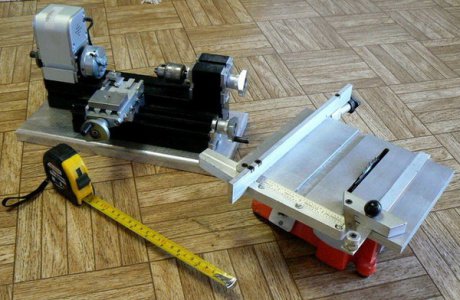
On the left is a small lathe and on the right a tiny table saw. The table saw was an off the shelf product from H-F and the lathe came from a Chinese eBay “store”. The table saw was about $45 IIRC and the lathe was just under $200.
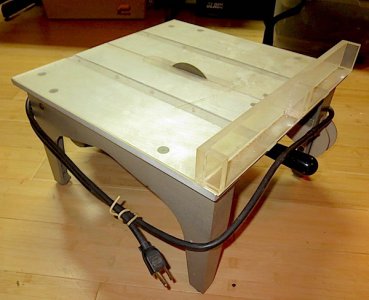
The table saw was very crude, the table wasn’t perpendicular to the saw blade, there was no rip fence nor was there a miter gauge. The motor was mounted in a cast “vee” not machined. The motor switch was downright dangerous looking and was the first thing that I replaced !
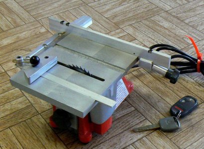
I removed the table and the motor and machined the “vee” where the motor mounted so that it was perpendicular to the mechanism that supported the table at a selected height. The cast aluminum table was fly-cut flat and two slots milled for the miter gauge. The front of the table (it’s hard to see) was tapered with a dovetail cutter.
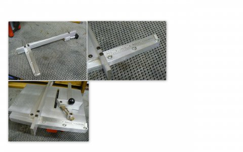
The rip fence has a matching taper and can be locked securely at any point along the table using the clamp mechanism at the rear of the fence.
The small miter gauge can be adjusted to any angle from 0 to 45 degrees. A very shallow slot was milled in the front of the table to accommodate a six inch machinist scale. The scale was mounted and carefully adjusted for the use of the miter gauge. The miter gauge alignment mark, when lined up with any graduation on the scale, will cut a part to that dimension.
This project came into being when I gashed my thumb using my full-size table saw to cut small hardwood keys. Even with a zero clearance insert, the thickness and coarse teeth of the saw blade are not appropriate for small, precise parts.
This little saw gets used often for woodworking projects: making keys, trimming dowels to length, mitering small picture frame joints - any application requiring precision cutting on small parts. It is capable of much more precision with less splintering than any of my other wood saws (I have five but they are all too large for this kind of work).
The little lathe, likewise, is intended to produce small parts, less than .090 diameter typically. I can make small parts on a little Emco 8 x 18 but the tiny lathe is handier. As received, the lathe headstock and tailstock were not well aligned and neither was parallel with the carriage ways.
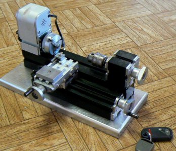
The lathe was cleverly designed, based on an extruded hard-anodized aluminum base with dovetails on every surface. The headstock and tailstock also have dovetails as does the carriage way extrusion. All of these parts are held together by pairs of cast aluminum tapered keys that expand when a screw is tightened.
These keys were the weak link in the design. They couldn’t be tightened adequately nor did they remain tight during cutting vibration. The small lathe chattered even during very light cuts. I attempted to solve several problems by discarding the adjustable keys and making non-adjustable keys from “Delrin”.
The new keys, with one exception, are a press fit with the dovetails extruded in the lathe base and carriage way extrusion. The keys are machined as one solid piece, configured as two male dovetails, back to back. The dimensions were designed so that the male dovetails securely lock any two of the various parts of the lathe together with no possibility of loosening under vibration.
Delrin was chosen for the keys rather than metal for several reasons. The dimensions do not have to be extremely precise to achieve a heavy press fit – the material will deform slightly to fit the dovetail but remain elastic.
I hoped to reduce chatter by locking all of the parts together much more securely than the original aluminum tapered clamps. Perhaps a bit of damping from the more elastic dovetail clamps would also be helpful.
(FWIW, making all of these Delrin dovetail parts was a real pain in the neck ! Even with sharp tooling, there was deflection and multiple spring passes were required to bring the parts to finish dimension.)
The tailstock of the small lathe didn’t include nor could it readily accommodate a drill chuck. A center was included that attached over a threaded portion of the tailstock ram. I adapted a ¼ inch drill chuck to fit the tailstock, as can be seen. Aligning the axis of the tailstock with the headstock centerline and parallel with the carriage travel was tricky and ended up being a compromise.
The tailstock extrusion has cast aluminum covers at front and rear, attached with four screws each. There was sufficient clearance in the cover mounting holes to make adjustments to the tailstock ram location. Painstaking trial and error corrections were made until a compromise was reached between the three axis. A similar process was used to align the headstock.
Delrin dovetail blocks were also made to mount the tailstock to the base extrusion. However they were dimensioned to be a press fit in the tailstock but a sliding fit with the dovetails in the base. The rear vee block is drilled and tapped longitudinally then slit part way along the tapped hole. A socket head set screw inserted in the tapped hole locks the tailstock at the desired location. (A long hex key at the end of the base is inserted to tighten the set screw.)
The small motor was powered by a 12 volt “wall wart” which provided a spindle speed somewhere in excess of 2500 RPM. I discarded this primitive power supply and used a variable power supply to adjust the motor speed within reasonable limits (about 1000 to 3000 RPM).
There is a tiny 3-jaw chuck threaded to the headstock spindle and it works surprisingly well. The chucked work is reasonably concentric with the spindle axis. However, it’s my intention to adapt another ¼ drill chuck (with a thru hole) to the spindle. The original chuck is made from cast mystery metal and will likely wear quickly.
I need to make a decent tool holder for the little lathe. The current configuration is a simple clamp that secures a 3/16 cutting tool to the cast aluminum table. It is sturdy enough but tedious and time consuming to adjust.
Five special Delrin keys, press fitted into the dovetails of the base and the carriage way extrusion, were drilled and tapped. A one inch thick piece of aluminum jig plate was machined as a base plate for the small lathe. The base plate was drilled and counter-bored from the far side for mounting screws. The base plate edges received some contouring with a 3/8 inch carbide router cutter.
These little tools are not intended to be anything like the beautiful functional and miniature replicas of real machine tools that are produced by dedicated and amazingly precise hobby craftsmen. The pair of machines was intended to fill a niche purpose – they cannot do anything that I can’t do with existing machinery but they are much easier and safer to use and in some cases more effective.
There are a couple of improvements that need to be made and I still want to make a small drill press, something a bit smaller than a Dumore but with much more precision/quality than a Dremel tool in a stand.
But the modifications, as you can imagine, were a lot of fun. I have a few more things that I want to do to them in the future.

On the left is a small lathe and on the right a tiny table saw. The table saw was an off the shelf product from H-F and the lathe came from a Chinese eBay “store”. The table saw was about $45 IIRC and the lathe was just under $200.
The table saw was very crude, the table wasn’t perpendicular to the saw blade, there was no rip fence nor was there a miter gauge. The motor was mounted in a cast “vee” not machined. The motor switch was downright dangerous looking and was the first thing that I replaced !

I removed the table and the motor and machined the “vee” where the motor mounted so that it was perpendicular to the mechanism that supported the table at a selected height. The cast aluminum table was fly-cut flat and two slots milled for the miter gauge. The front of the table (it’s hard to see) was tapered with a dovetail cutter.
The rip fence has a matching taper and can be locked securely at any point along the table using the clamp mechanism at the rear of the fence.
The small miter gauge can be adjusted to any angle from 0 to 45 degrees. A very shallow slot was milled in the front of the table to accommodate a six inch machinist scale. The scale was mounted and carefully adjusted for the use of the miter gauge. The miter gauge alignment mark, when lined up with any graduation on the scale, will cut a part to that dimension.
This project came into being when I gashed my thumb using my full-size table saw to cut small hardwood keys. Even with a zero clearance insert, the thickness and coarse teeth of the saw blade are not appropriate for small, precise parts.
This little saw gets used often for woodworking projects: making keys, trimming dowels to length, mitering small picture frame joints - any application requiring precision cutting on small parts. It is capable of much more precision with less splintering than any of my other wood saws (I have five but they are all too large for this kind of work).
The little lathe, likewise, is intended to produce small parts, less than .090 diameter typically. I can make small parts on a little Emco 8 x 18 but the tiny lathe is handier. As received, the lathe headstock and tailstock were not well aligned and neither was parallel with the carriage ways.

The lathe was cleverly designed, based on an extruded hard-anodized aluminum base with dovetails on every surface. The headstock and tailstock also have dovetails as does the carriage way extrusion. All of these parts are held together by pairs of cast aluminum tapered keys that expand when a screw is tightened.
These keys were the weak link in the design. They couldn’t be tightened adequately nor did they remain tight during cutting vibration. The small lathe chattered even during very light cuts. I attempted to solve several problems by discarding the adjustable keys and making non-adjustable keys from “Delrin”.
The new keys, with one exception, are a press fit with the dovetails extruded in the lathe base and carriage way extrusion. The keys are machined as one solid piece, configured as two male dovetails, back to back. The dimensions were designed so that the male dovetails securely lock any two of the various parts of the lathe together with no possibility of loosening under vibration.
Delrin was chosen for the keys rather than metal for several reasons. The dimensions do not have to be extremely precise to achieve a heavy press fit – the material will deform slightly to fit the dovetail but remain elastic.
I hoped to reduce chatter by locking all of the parts together much more securely than the original aluminum tapered clamps. Perhaps a bit of damping from the more elastic dovetail clamps would also be helpful.
(FWIW, making all of these Delrin dovetail parts was a real pain in the neck ! Even with sharp tooling, there was deflection and multiple spring passes were required to bring the parts to finish dimension.)
The tailstock of the small lathe didn’t include nor could it readily accommodate a drill chuck. A center was included that attached over a threaded portion of the tailstock ram. I adapted a ¼ inch drill chuck to fit the tailstock, as can be seen. Aligning the axis of the tailstock with the headstock centerline and parallel with the carriage travel was tricky and ended up being a compromise.
The tailstock extrusion has cast aluminum covers at front and rear, attached with four screws each. There was sufficient clearance in the cover mounting holes to make adjustments to the tailstock ram location. Painstaking trial and error corrections were made until a compromise was reached between the three axis. A similar process was used to align the headstock.
Delrin dovetail blocks were also made to mount the tailstock to the base extrusion. However they were dimensioned to be a press fit in the tailstock but a sliding fit with the dovetails in the base. The rear vee block is drilled and tapped longitudinally then slit part way along the tapped hole. A socket head set screw inserted in the tapped hole locks the tailstock at the desired location. (A long hex key at the end of the base is inserted to tighten the set screw.)
The small motor was powered by a 12 volt “wall wart” which provided a spindle speed somewhere in excess of 2500 RPM. I discarded this primitive power supply and used a variable power supply to adjust the motor speed within reasonable limits (about 1000 to 3000 RPM).
There is a tiny 3-jaw chuck threaded to the headstock spindle and it works surprisingly well. The chucked work is reasonably concentric with the spindle axis. However, it’s my intention to adapt another ¼ drill chuck (with a thru hole) to the spindle. The original chuck is made from cast mystery metal and will likely wear quickly.
I need to make a decent tool holder for the little lathe. The current configuration is a simple clamp that secures a 3/16 cutting tool to the cast aluminum table. It is sturdy enough but tedious and time consuming to adjust.
Five special Delrin keys, press fitted into the dovetails of the base and the carriage way extrusion, were drilled and tapped. A one inch thick piece of aluminum jig plate was machined as a base plate for the small lathe. The base plate was drilled and counter-bored from the far side for mounting screws. The base plate edges received some contouring with a 3/8 inch carbide router cutter.
These little tools are not intended to be anything like the beautiful functional and miniature replicas of real machine tools that are produced by dedicated and amazingly precise hobby craftsmen. The pair of machines was intended to fill a niche purpose – they cannot do anything that I can’t do with existing machinery but they are much easier and safer to use and in some cases more effective.
There are a couple of improvements that need to be made and I still want to make a small drill press, something a bit smaller than a Dumore but with much more precision/quality than a Dremel tool in a stand.


