- Joined
- Jul 9, 2014
- Messages
- 613
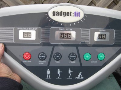
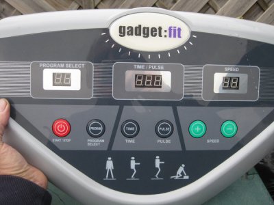
I live in Great Britain aka the United Kingdom or England ( whatever you know it as ) I was given a fully working 220 =240 volt AC fitness massager a long time ago ..the sort that has a vibrating floor plate that you can alter the speed on and set the machine for a times to run or a variable programme .
I have had a stroke and the resultant blood clotting has now made the use of the machine very silly as it may loosen further clots in me and kill me.
So to make lemonade out of lemons I have a hankering to make some sort of device for my lathe..I don't have a milling machine... sadly .
One of my ideas is to use it to make a tool post grinder or a polisher or perhaps even use it to power the lathe as it is labeled as a 220 v 600 w DC motor ( I'm not sure if that DC designation is correct or not for I guess it would run powered up to the equivalent of 300 volts AC or so ).
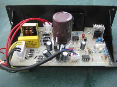
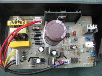
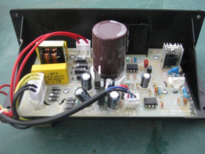
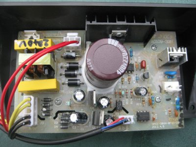
The diodes on the control panel imply it is a meaty 220 AC to ??? DC rectifier , the motor seems to be a well made two brush motor .
I'm trying to find any info using the bits to do such things but I keep hitting a wall of silence wrt service sheets or wiring diagrams or even the motor .
Can any of you with the special detective bent needed help me in finding out information.
I'll take a load of pictures tomorrow and put them in the thread .
Details found so far :-
Equipment label detail:-
Fitness master item No HM01 08VM 230 v 50 hz 600 w
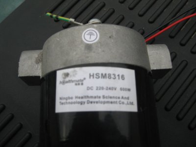
Detail on the motor's label :-
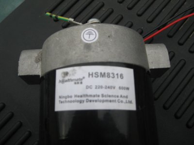
HSM 8316 Healthmate DC 220- 240 v 600 w
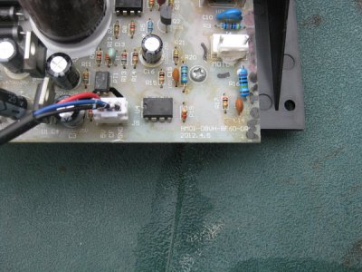
Main incoming power circuit board details or apparent details :-
40109 - 39B
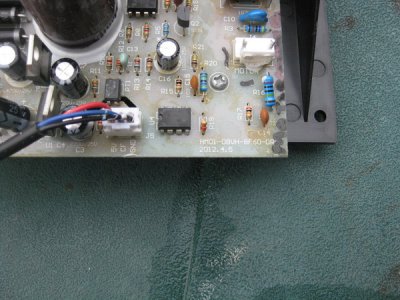
HM * 01 - 08VH -8F60 -DR(*** O )
( * means it may be a D , a zero or an O) , ( *** means either zero or an O).
It also bears markings that appear to be HF1210C * (* could be a 3 ,8 or a B )
Any help or advice you can give me or point me to would be greatly appreciated .
Thanks
Dave
I have had a stroke and the resultant blood clotting has now made the use of the machine very silly as it may loosen further clots in me and kill me.
So to make lemonade out of lemons I have a hankering to make some sort of device for my lathe..I don't have a milling machine...
 sadly .
One of my ideas is to use it to make a tool post grinder or a polisher or perhaps even use it to power the lathe as it is labeled as a 220 v 600 w DC motor ( I'm not sure if that DC designation is correct or not for I guess it would run powered up to the equivalent of 300 volts AC or so ).
The diodes on the control panel imply it is a meaty 220 AC to ??? DC rectifier , the motor seems to be a well made two brush motor .
I'm trying to find any info using the bits to do such things but I keep hitting a wall of silence wrt service sheets or wiring diagrams or even the motor .
Can any of you with the special detective bent needed help me in finding out information.
I'll take a load of pictures tomorrow and put them in the thread .
Details found so far :-
Equipment label detail:-
Fitness master item No HM01 08VM 230 v 50 hz 600 w
Detail on the motor's label :-
HSM 8316 Healthmate DC 220- 240 v 600 w
Main incoming power circuit board details or apparent details :-
40109 - 39B
HM * 01 - 08VH -8F60 -DR(*** O )
( * means it may be a D , a zero or an O) , ( *** means either zero or an O).
It also bears markings that appear to be HF1210C * (* could be a 3 ,8 or a B )
Any help or advice you can give me or point me to would be greatly appreciated .
Thanks
Dave


