- Joined
- Nov 7, 2019
- Messages
- 436
Too many projects active as usual so might as well start another one.
Been wanting to build one for myself for 4+ years but always pushing it forwards despite the fact that it would have made a lot of my other projects easier.
Finally got the push I "needed" when my dads health started declining to the point where working on cars(hobby) isn't feasible and he's instead looking at getting into knife making.
Granted you don't need a massive belt grinder for that, but it sure helps.
Economy in general being what it is, and me being a student atm, seriously limits the budget so it will mostly be from things I've collected and scrap I can reuse.
Obviously there's a whole load of different designs available online but I drew this up combining different features I liked.
Designed to use 50x50mm tubing but things will change depending on what I have in stock.
Completely separate "sliders" for the belt grinder and the working surface should allow some better flexibility when swapping between jigs and and grinding different shapes.
The motor roughly sketched is not the type I will be using, purely illustrative because that's what I thought I'd use.
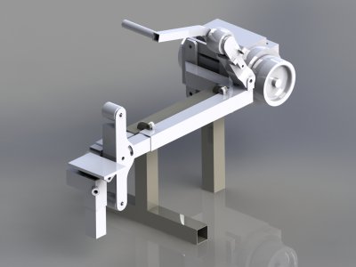
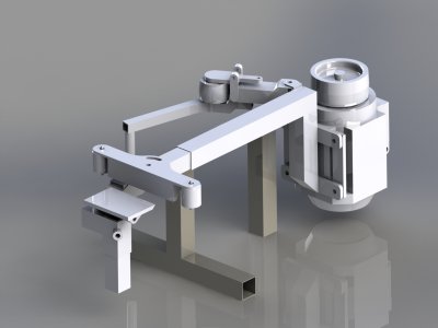
Incredibly messy pictures, like everything else atm, but still.
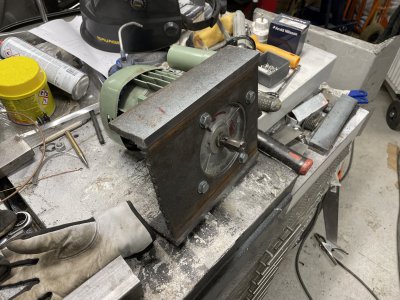
Kinda started backwards here by sawing off an I-beam to make it into a C-beam and then boring out for the motor flange.
The motor shown is only 750W if I remember correctly, I have another that's 1.5kW that has the same flange and will be mounted on the final version.
Been trying to get faster when fabricating stuff instead of spending 40 hours at the mill ... I often don't need the accuracy the mill gives me.
The workflow for this part was pretty much:
-Used the metal bandsaw to take most of the steel off to make the I into a C.
-Find the biggest holesaw I have, 100mm-ish, and mark it's perimeter where I wanted my 130mm hole and then drill 10mm holes in a few places along that perimeter.
-Mount it to the drillpress table and holesaw it, the 10mm holes makes chip evacuation much faster/effective.
-Mount it in the mill to bore the hole to final size and surface where I cut the flanges off the I-beam.
-Remount it upside down to bore a tiny bit on the inside of the flanges so the motor would clear(the fillet was just barely in the way)
-Finally put the motor in and use a hole transferpunch to locate the holes and drill them in the drillpress.
Quite a few steps but still took me maybe 20% of the time it would've taken me to do it "my usual way" and still "accurate enough".
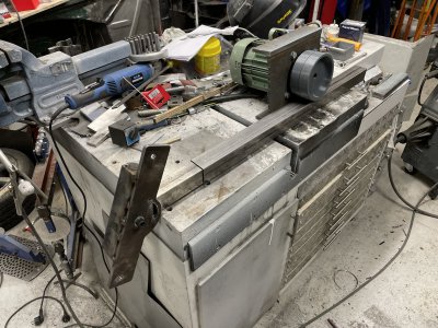
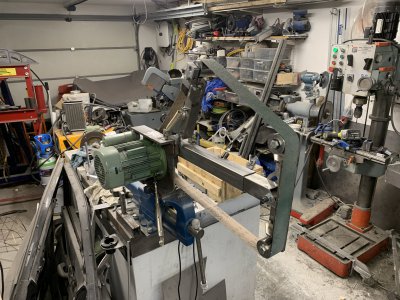
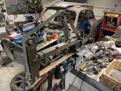
Then I started mocking up the belt-grinder-slider-thing.
It's two "seamless" tubes that have a decent fit in eachother.
The platten is random junk ~5-10mm thick.
Marked the holes by hand, drilled on drillpress and did the curved slot in the mill("CNC" so I don't need rotary table etc)
Cut most of the contours with the bandsaw and then just milled the important edges and used the angle grinder to clean up everything else, mostly working to a scribed line. At least felt way faster than milling it all.
A bit of a gap here where a lot happened.
-Tensioner arm is made, springloaded at the moment but I'm fairly sure I need to give the spring more leverage to apply more belt tension.
-Tracking can be adjusted by tilting the tensioner wheel, it's currently radiused(not sure what the correct term is) to help the belt track but the radius itself was guesswork so will be interesting to see how well it works in final version.
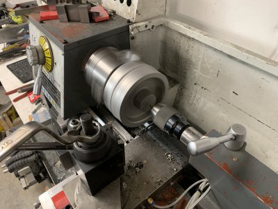
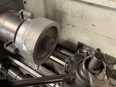
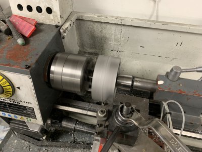
-The tensioner wheel is made from 3x 20mm thick discs, turned slightly above final size, welded, turned to final size and then turned bearing pockets on both sides.
-The roller wheels are instead made from 2x 20mm thick discs each, pressed into the ends of a 52mm tube. Aligned and faced the ends, welded the discs to the tube and turned bearing pockets on both sides. Both rollers and tensioner was extremely time consuming and I should just have cast roundstock from aluminium...
-Roller and tensioner wheels have turned spacers inside of them so the bearings don't get crushed when I tighten the bolts, this worked really well.
-Locking bolt added to the slider, angled on purpose to push the inner part down into a corner.
-Temporary plastic drivewheel just so I can mount the belt.
-Pushing the band forward manually, the tracking seems to work but there is a lot of slop in the plastic drive wheel so the next step is to fix that..
This was rather fun tbh.
Needed a bigger/taller flask which I threw together from random bits of plywood/junk pineboards. I made it as one big box and let the glue set before cutting it apart on the tablesaw to have two perfectly aligned boxes.
Added some metal strips to align both to eachother and two through holes to hold them together.
Then printed, primed and painted some shapes, initially I want to cast the drivewheel but might also try casting the roller and tensioner wheels so I prepped those too.
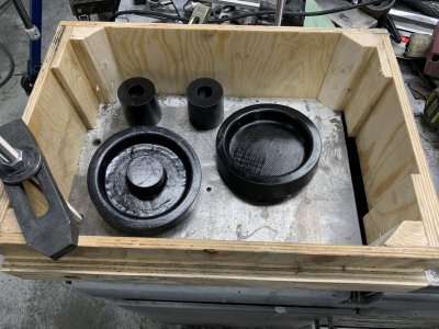
Flask ended up being much bigger than I need, but this makes it much easier to make gating system etc and I'm sure I will manage to fill this up eventually when I get a bit more brave and cast several things at a time.
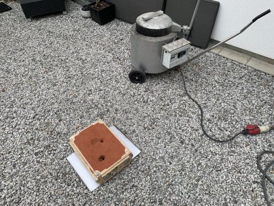
Main mistake here is that I didn't have the riser and pouring cup already in when I thumped the sand, would probably have both saved me some time and effort.
I had already "guessed" where the riser should be, completely missing and hitting the edge of the pulley.
After the photo was taken I carefully removed sand to make a pouring coup and gating system.
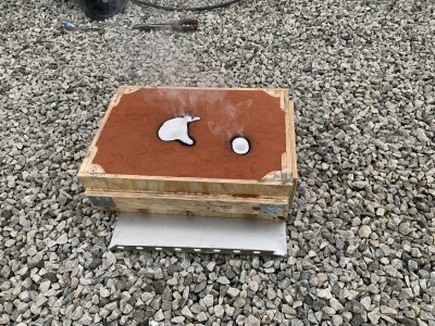
I have little to no experience with this but I suspect my gating system was too big considering how fast the form filled.
I really love my electric furnace, quite and easy to use, it is however quite slow at the moment with 1 out of 2 heater coils being broken and difficult to repair without breaking the other one..
Calculations said the pulley should be around 2kg so I took 3.3kg of material just to be extremely safe.
The ingots I'm using are melted down car rims ie generic aluminium alloy, I'm really glad I spent all that time making ingots because the melt was incredibly clean with barely any slag to remove whereas before I needed to remove significant amounts before I could even think of pouring something.
Judging by the size of the ingot that was left over after filling the mold, I could probably have used 2.5kg and still had safety margin.
Overall I'm extremely happy with my results, considering my big lack of experience with casting.
There was quite a bit of smoking when I poured but the melt itself seemed calm and not bubbly/turbulent.
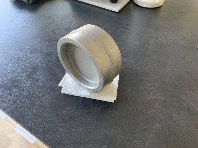
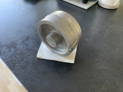
Carefully looking over the casting there's various "issues":
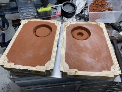
-Flashing around the wheel, to be expected I guess but I probably made it worse by not packing the sand tightly enough around the perimeter.
-Pitting here and there of varying degrees, I'm guessing this could be from the melt being too hot and/or the mold being too poorly ventilated and not able to release the gas/smoke created internally. I've seen some poke a bunch of holes to help the gasses escape so might try that next time.
-The perimeter is missing a tiny bit of material both where the riser(left pic, bottom) and feed(right pic, to the right) were.
I think that:
1. my feed was too tall/big, basically acting like a big/bad riser and causing uneven shrinking. Next time I will try making it smaller and not connected so far out on an edge where it cools/shrinks faster.
2. Similar issue with the riser, connected in a way that it sucked material from the part as it cooled. Should've probably increased it's diameter and "connected" it to the middle of the face then just adding tiny vent holes around the raised edge.
Most other defects can probably be blamed on my moldwork, some edges etc did not seem to hold up well when I removed the plugs.
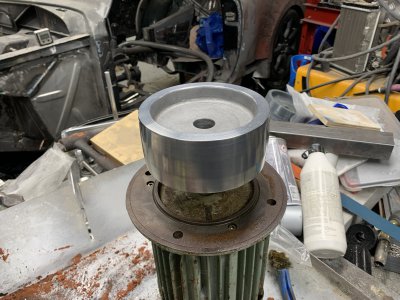
Next up I think I will drill out the center for the motorshaft, mount that on an arbor and clean up the surfaces.
Been wanting to build one for myself for 4+ years but always pushing it forwards despite the fact that it would have made a lot of my other projects easier.
Finally got the push I "needed" when my dads health started declining to the point where working on cars(hobby) isn't feasible and he's instead looking at getting into knife making.
Granted you don't need a massive belt grinder for that, but it sure helps.
Economy in general being what it is, and me being a student atm, seriously limits the budget so it will mostly be from things I've collected and scrap I can reuse.
Obviously there's a whole load of different designs available online but I drew this up combining different features I liked.
Designed to use 50x50mm tubing but things will change depending on what I have in stock.
Completely separate "sliders" for the belt grinder and the working surface should allow some better flexibility when swapping between jigs and and grinding different shapes.
The motor roughly sketched is not the type I will be using, purely illustrative because that's what I thought I'd use.


Incredibly messy pictures, like everything else atm, but still.
Kinda started backwards here by sawing off an I-beam to make it into a C-beam and then boring out for the motor flange.
The motor shown is only 750W if I remember correctly, I have another that's 1.5kW that has the same flange and will be mounted on the final version.
Been trying to get faster when fabricating stuff instead of spending 40 hours at the mill ... I often don't need the accuracy the mill gives me.
The workflow for this part was pretty much:
-Used the metal bandsaw to take most of the steel off to make the I into a C.
-Find the biggest holesaw I have, 100mm-ish, and mark it's perimeter where I wanted my 130mm hole and then drill 10mm holes in a few places along that perimeter.
-Mount it to the drillpress table and holesaw it, the 10mm holes makes chip evacuation much faster/effective.
-Mount it in the mill to bore the hole to final size and surface where I cut the flanges off the I-beam.
-Remount it upside down to bore a tiny bit on the inside of the flanges so the motor would clear(the fillet was just barely in the way)
-Finally put the motor in and use a hole transferpunch to locate the holes and drill them in the drillpress.
Quite a few steps but still took me maybe 20% of the time it would've taken me to do it "my usual way" and still "accurate enough".

Then I started mocking up the belt-grinder-slider-thing.
It's two "seamless" tubes that have a decent fit in eachother.
The platten is random junk ~5-10mm thick.
Marked the holes by hand, drilled on drillpress and did the curved slot in the mill("CNC" so I don't need rotary table etc)
Cut most of the contours with the bandsaw and then just milled the important edges and used the angle grinder to clean up everything else, mostly working to a scribed line. At least felt way faster than milling it all.

A bit of a gap here where a lot happened.
-Tensioner arm is made, springloaded at the moment but I'm fairly sure I need to give the spring more leverage to apply more belt tension.
-Tracking can be adjusted by tilting the tensioner wheel, it's currently radiused(not sure what the correct term is) to help the belt track but the radius itself was guesswork so will be interesting to see how well it works in final version.
-The tensioner wheel is made from 3x 20mm thick discs, turned slightly above final size, welded, turned to final size and then turned bearing pockets on both sides.
-The roller wheels are instead made from 2x 20mm thick discs each, pressed into the ends of a 52mm tube. Aligned and faced the ends, welded the discs to the tube and turned bearing pockets on both sides. Both rollers and tensioner was extremely time consuming and I should just have cast roundstock from aluminium...
-Roller and tensioner wheels have turned spacers inside of them so the bearings don't get crushed when I tighten the bolts, this worked really well.
-Locking bolt added to the slider, angled on purpose to push the inner part down into a corner.
-Temporary plastic drivewheel just so I can mount the belt.
-Pushing the band forward manually, the tracking seems to work but there is a lot of slop in the plastic drive wheel so the next step is to fix that..


This was rather fun tbh.
Needed a bigger/taller flask which I threw together from random bits of plywood/junk pineboards. I made it as one big box and let the glue set before cutting it apart on the tablesaw to have two perfectly aligned boxes.
Added some metal strips to align both to eachother and two through holes to hold them together.
Then printed, primed and painted some shapes, initially I want to cast the drivewheel but might also try casting the roller and tensioner wheels so I prepped those too.

Flask ended up being much bigger than I need, but this makes it much easier to make gating system etc and I'm sure I will manage to fill this up eventually when I get a bit more brave and cast several things at a time.
Main mistake here is that I didn't have the riser and pouring cup already in when I thumped the sand, would probably have both saved me some time and effort.
I had already "guessed" where the riser should be, completely missing and hitting the edge of the pulley.

After the photo was taken I carefully removed sand to make a pouring coup and gating system.
I have little to no experience with this but I suspect my gating system was too big considering how fast the form filled.

I really love my electric furnace, quite and easy to use, it is however quite slow at the moment with 1 out of 2 heater coils being broken and difficult to repair without breaking the other one..
Calculations said the pulley should be around 2kg so I took 3.3kg of material just to be extremely safe.
The ingots I'm using are melted down car rims ie generic aluminium alloy, I'm really glad I spent all that time making ingots because the melt was incredibly clean with barely any slag to remove whereas before I needed to remove significant amounts before I could even think of pouring something.
Judging by the size of the ingot that was left over after filling the mold, I could probably have used 2.5kg and still had safety margin.


Overall I'm extremely happy with my results, considering my big lack of experience with casting.
There was quite a bit of smoking when I poured but the melt itself seemed calm and not bubbly/turbulent.
Carefully looking over the casting there's various "issues":
-Flashing around the wheel, to be expected I guess but I probably made it worse by not packing the sand tightly enough around the perimeter.
-Pitting here and there of varying degrees, I'm guessing this could be from the melt being too hot and/or the mold being too poorly ventilated and not able to release the gas/smoke created internally. I've seen some poke a bunch of holes to help the gasses escape so might try that next time.
-The perimeter is missing a tiny bit of material both where the riser(left pic, bottom) and feed(right pic, to the right) were.
I think that:
1. my feed was too tall/big, basically acting like a big/bad riser and causing uneven shrinking. Next time I will try making it smaller and not connected so far out on an edge where it cools/shrinks faster.
2. Similar issue with the riser, connected in a way that it sucked material from the part as it cooled. Should've probably increased it's diameter and "connected" it to the middle of the face then just adding tiny vent holes around the raised edge.
Most other defects can probably be blamed on my moldwork, some edges etc did not seem to hold up well when I removed the plugs.
Next up I think I will drill out the center for the motorshaft, mount that on an arbor and clean up the surfaces.


