Advice on 3D printed gear

Oh I see you meant a brass insert for just the set screw. I think you’d be tight on space for that.
That's right, and yes, it would be tight, but not too tight, I think. The question is moot, however, since we have seen better solutions here.
I agree the outer collar would work well. That lets the plastic print define the bore and uses the collar for set-screw threads.
Exactly.
 
Heat set inserts work REALLY well. I've never failed one! I would never expect to be able to push one out with a setscrew. Maybe with a hex head bolt... the bore is likely to fail first!

Sent from my SM-G715A using Tapatalk
 
I like that idea! It is extremely simple and inexpensive:

View attachment 418974
Pleasure but it is not an original idea, I have seen it done on a number of 3D printed designs.
I normally design it with a hex shaped hole that I slot out. For better grip you could use a more rectangular plate that you tap yourself

Sent from my SM-S908E using Tapatalk
 
That is another great idea! It is a little bit more expensive, and just a bit more work, but should provide less of an imbalance than a captive nut. If the captive nut solution provides too much vibration at high speeds, I think I will try it.
Excess vibration is unlikely in your application so the simpler captive nut will probably do the trick. BTW you don't need the nut's slot centered in the hub, it could be designed so the nut is just proud of the flat on the encoder shaft. That would leave a lot more meat for the nut to push against when the set screw is tightened down on the shaft.

As far as expense goes, it all depends on how well "stocked" your scrap box is. I rarely throw any nubbins away so the collar scheme probably wouldn't incur any cost except perhaps for the set screw.
 
Excess vibration is unlikely in your application so the simpler captive nut will probably do the trick.
I think you are correct. We shall see.
BTW you don't need the nut's slot centered in the hub, it could be designed so the nut is just proud of the flat on the encoder shaft. That would leave a lot more meat for the nut to push against when the set screw is tightened down on the shaft.
Yes, I know. See my design above.
As far as expense goes, it all depends on how well "stocked" your scrap box is. I rarely throw any nubbins away so the collar scheme probably wouldn't incur any cost except perhaps for the set screw.
I don't think I have any round stock of an appropriate size. Not only that, but whether it is in my drop bin or I have to buy it new, it still costs money, whether already paid or not.
 
Pleasure but it is not an original idea, I have seen it done on a number of 3D printed designs.
I normally design it with a hex shaped hole that I slot out. For better grip you could use a more rectangular plate that you tap yourself
Yes, I do that quite often myself when there is ready access to the outside surface of the part. It hadn't occurred to me to create a slot in the middle of a printed piece. It only engages 2 of the flats, rather than all 6, but that is plenty.
 
The machining on the ELS is complete! I am just waiting for a timing belt to come in for the Servo to Lead Screw link. I will provide some photos when the belt comes in. I want to thank wobblyhand for his offer to broach the Lead Screw pulley. Unfortunately, it turned out he didn't have the necessary sized broach, but the helpful attitude is an extremely valuable thing. The key is a rather tiny 3mm square pin. I suppose I could have taken out the Lead Screw and machined a wider slot, but instead I decided to mill out a slot in the pulley.

I took a piece of 1/2" Aluminum plate, cut out a 2.5" chunk, and milled it square. I took my nearest sized hole saw, drilled a hole in the center of the block, and then used a boring head to carefully expand the hole to a close fit over the pulley hub. I drilled 4 holes on the sides of the block, 2 of them 5mm and 2 of them 4.2mm diameter. I tapped the 4.2mm holes and inserted set screws. Then I put 2 set screws into the existing tapped holes in the pulley, driving them in below the surface.
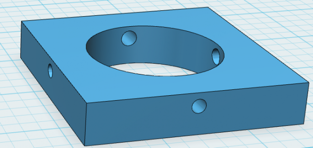
Pulley Block Fixture.PNG

I seated the pulley into the block, and withdrew the set screws out of the hub part way into the 5mm clearance holes in the block. Then I seated the set screws in the block down on the pulley on the other two sides.
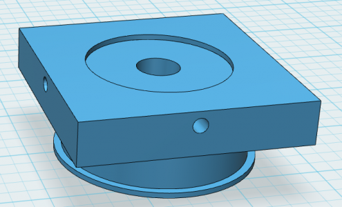
Pulley Block with Pulley.PNG

Setting the pulley face down on a pair of parallels in the vise, I took a 3mm end mill with extra long flutes I had on hand and plunged it down the side of the hub in line with one of the set screw holes. I took a needle file and squared off the bottom of the slot by hand. It fits perfectly!
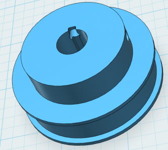
Pulley with Broach.PNG

The 3D printed gear on the encoder seems to be working a treat. It is very quiet - far, far quieter than the stock cast iron gears supplied with the lathe. I ran the lathe all the way up to 3000 RPM for several minutes, and the result was pleasantly non-dramatic. Running the lathe over 1200 RPM or so always used to make me slightly uneasy, not to mention having to wear hearing protectors if I was doing any work for an extended period time. Now it purrs like a kitten.
 
Back
Top