- Joined
- Sep 10, 2020
- Messages
- 34
On my previous Rockwell 21-100 mill build, the 3rd comment from OTmachine stated,
"Make sure and let us know your method of quill return spring installation". Well better late than never, here it is but on a 21-122 dual spindle, so new thread.
This method is based on the popular technique for adding a mill table motor drive to the table screw by extending the shaft.
The 1st and 2nd photos shows the disassembled parts. Oh, btw I can't take credit for this. My 21-122 came with it, but I was on the right track eyeing a clockspring on an abandoned bench drill press. Anyway, There are 4 custom made components.
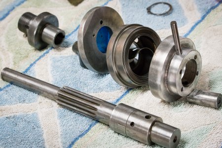
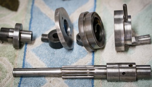
#1. To the right of the stock threaded fine feed adapter (top left) is a flat mounting disc (steel) that is screwed to the head casting being a foundation for #2 and#3.
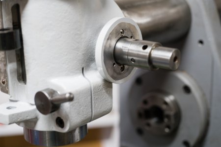
#2. Machined of steel is a cup shaped clockspring holder with clockspring inside. As you can see, there is a lot of clockspring in there.
#3. A quill pinion shaft extension slip fitted and pinned to the pinion shaft. The leftmost hole to the right of the seam between the 2 parts is where the capped pin goes that secures the end of the clockspring. I just noticed these photos do not show the pin that secures the extension to the original pinion shaft. The other visible hole is for pinning the #4 part to the now called pinion shaft assembly.
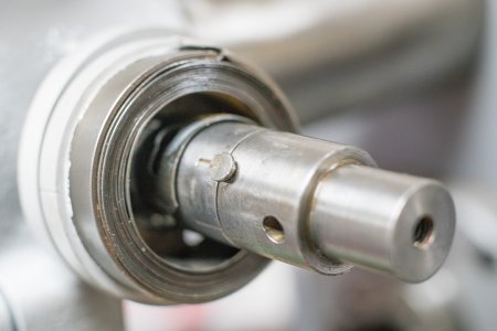
#4. I will call this the quill return cowl. It is shown with the pin ready to go thru the pinion shaft extension. It is made of aluminum, covers the clockspring cup, and has 4 available holes for the handle pin to locate to.
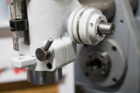
I will say that I had to fiddle and modify a few of the parts to get it to operate smoothly. The #1 mounting disc could be mounted in 2 possible positions, likewise the pin that goes thru the #4 cowl. The 2 screws that secured the #1 mounting disc were in bad condition and 2 more had to be turned on the lathe to fit. And there was way too much clockspring for the job. I cut out 2 or 3 windings resulting in a more snappy and smooth action.
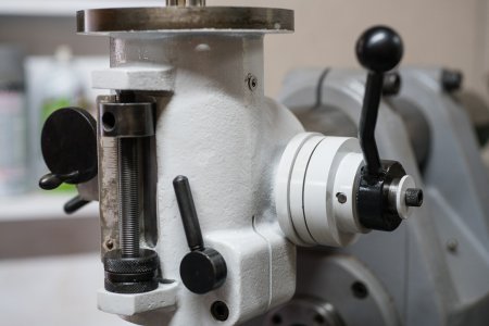
Well, there it is. I've tried to stay close to the original paint color as best as I can, so I've painted the pieces as they went back on. Bare parts got the black oxide finish. I'm getting close to a wrap on this one. I just have to work out the electricals. I will be controlling both motors with a VFD and a A/off/B rotary cam switch box. The horizontal spindle motor has no label, so I don't know if it is 1.5hp or the 1hp. If I knew it was the smaller 1hp, buying the VFD would be a little easier and cheaper. My horizontal motor weights exactly 49 lbs.
"Make sure and let us know your method of quill return spring installation". Well better late than never, here it is but on a 21-122 dual spindle, so new thread.
This method is based on the popular technique for adding a mill table motor drive to the table screw by extending the shaft.
The 1st and 2nd photos shows the disassembled parts. Oh, btw I can't take credit for this. My 21-122 came with it, but I was on the right track eyeing a clockspring on an abandoned bench drill press. Anyway, There are 4 custom made components.


#1. To the right of the stock threaded fine feed adapter (top left) is a flat mounting disc (steel) that is screwed to the head casting being a foundation for #2 and#3.

#2. Machined of steel is a cup shaped clockspring holder with clockspring inside. As you can see, there is a lot of clockspring in there.
#3. A quill pinion shaft extension slip fitted and pinned to the pinion shaft. The leftmost hole to the right of the seam between the 2 parts is where the capped pin goes that secures the end of the clockspring. I just noticed these photos do not show the pin that secures the extension to the original pinion shaft. The other visible hole is for pinning the #4 part to the now called pinion shaft assembly.

#4. I will call this the quill return cowl. It is shown with the pin ready to go thru the pinion shaft extension. It is made of aluminum, covers the clockspring cup, and has 4 available holes for the handle pin to locate to.

I will say that I had to fiddle and modify a few of the parts to get it to operate smoothly. The #1 mounting disc could be mounted in 2 possible positions, likewise the pin that goes thru the #4 cowl. The 2 screws that secured the #1 mounting disc were in bad condition and 2 more had to be turned on the lathe to fit. And there was way too much clockspring for the job. I cut out 2 or 3 windings resulting in a more snappy and smooth action.

Well, there it is. I've tried to stay close to the original paint color as best as I can, so I've painted the pieces as they went back on. Bare parts got the black oxide finish. I'm getting close to a wrap on this one. I just have to work out the electricals. I will be controlling both motors with a VFD and a A/off/B rotary cam switch box. The horizontal spindle motor has no label, so I don't know if it is 1.5hp or the 1hp. If I knew it was the smaller 1hp, buying the VFD would be a little easier and cheaper. My horizontal motor weights exactly 49 lbs.
Last edited:

