Years ago my old analog multimeter passed away. I had the bright idea to keep the meter, in case I will make something useful out of it later, and threw away the rest.
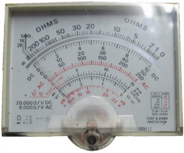
That “later” came a few days ago when I needed a way to test Equivalent Series Resistance (ESR) of some electrolytic capacitors that looked good but die quickly.
Let’s take the story from the beginning!
The need to test capacitors’ Equivalent Series Resistance (ESR) increases daily because more electrolytic capacitors are used into circuits where resistance causes problems. Especially now that switch-mode power supplies (SMPS's) have been commonly used in domestic PCs and TV's for a decade or so, one of the most likely components to fail is the humble electrolytic capacitor.
Why not use a readily available capacitor meter? Because when electrolytic capacitors go faulty, they normally don't lose their capacitance significantly (as is normally assumed). Rather their equivalent series resistance (ESR) goes high.
A capacitor ESR tester tests for this capacitor failure, reading the series resistance of the capacitor directly in ohms.
I will give some brief answers to some basic questions about ESR.
Why not buy a commercial one? Well, apart from the price, that is quite high for a meter like that, mainly for the joy of “making” it!
1. What Is ESR?
Every capacitor has some ESR. ESR is the electrical resistances in series with the capacitor plates. Electrolytic capacitors depend on a water-based electrolytic, soaked into a strip of porous material between the aluminum foil plates, to complete the outer electrical connection to the aluminum oxide dielectric coating on the anode foil.
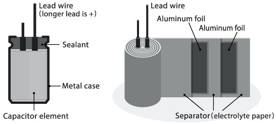
The electrolytic has electrical resistance which, along with the (negligible) resistance of the connecting leads and aluminum foil plates, forms the capacitors equivalent series resistance.
Normally the ESR has a very low value, which stays that way for many years unless the rubber seal is defective or the electrolytic is heated (the service life of electrolytic caps is approximately halved for every 10 degrees C increase in temperature). Then the electrolytics water component gradually dries out and the ESR increases with time.
As a result, the electrolytic gradually acts more and more like a capacitor with its own internal series resistor.
2. What Causes ESR To Change?
The most Common cause of high ESR is drying of the electrolyte solution. Drying occurs because of the evaporation of water in the electrolyte solution. The solution soaks the paper spacer between the two aluminum plates. The water carries the electrical charge from the negative aluminum plate to the surface of the insulating oxide on the positive plate. The oxide forms the capacitor’s dielectric and the negative charge on the surface of the oxide forms the negative capacitor plate. As the water evaporates, the electrical resistance increases.
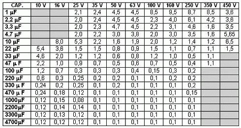
Manufacturers provide tables with acceptable ESR values for their capacitors.
3. Why is ESR so difficult to detect?
The circuits that measure ESR must be able to ignore other capacitor parameters, including the capacitive reactance at a given frequency. It would be handy if we could just reach inside with a DC ohmmeter and measure the resistance in series with each metal plate. We can’t do that, because the capacitor blocks any attempt to measure with DC. Therefore, we must use an AC signal to isolate a DC failure mode.
The ESR meter described here is used to measure the series resistance of a capacitor either in-circuit or out-of circuit. As ERS is usually expressed as the maximum value at around 100 KHz for the tantalum and aluminum electrolytic capacitors, the meter uses this frequency to measure the impedance of the capacitor. For Capacitors larger than a few uF this is approximately equal to the ESR.
Meter description
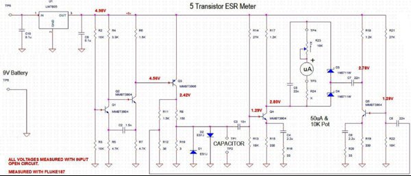
This is a simple ESR meter designed by eevblog member Jay_Diddy_B. (https://www.eevblog.com/forum/projects/5-transistor-esr-meter-design/msg171364/#msg171364) It uses a 50 uA linear meter (one from an old multimeter fits the bill nicely) and a handful of easy to find components:
5 general purpose transistors, a 5V regulator, 5 diodes, a few capacitors and a dozen resistors. The only critical parts, apart from the meter, are the two diodes D3 and D4. Diodes should be small signal Schottky 1N5711 or 1N34A, Ge diodes, OA91 or similar. Common diodes like BAT54 have too much capacitance and they will affect the meter scale (i.e. make it less sensitive). The circuit takes its power from any DC source 9 to 15V, you can omit the regulator and have the circuit work directly from 3 or 4 AA batteries.
Schematic
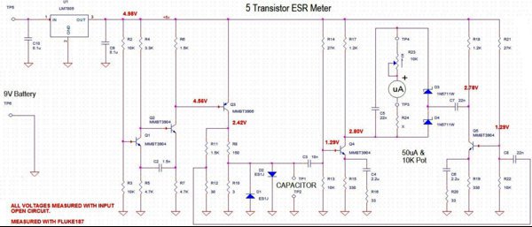
The maximum voltage on the capacitor under test is 100mV. This allows for in-circuit capacitor testing. ESR meter do not need to be precise, it most instances a bad capacitor will have an ESR many times that of a good one.
Construction
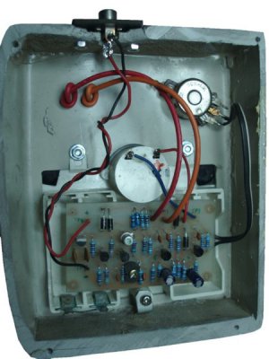
All components except meter and 10 k potentiometer are mounted on a single sided printed circuit board. Figure 1 shows the component side of the PCB and the position of each component, at the bottom you can see the copper track pattern.
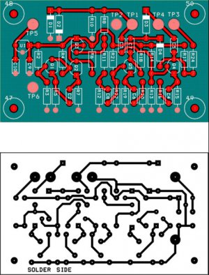
PCB construction
The problem most people have is getting the track pattern off the paper and onto the board and still maintaining a reasonable amount of accuracy. To make the PCB you will need a piece of single sided board, a printout of the copper track pattern, PCB pen and etch. The board was made using the following method:
Print the copper track pattern on paper. Clean the PCB with wire wool and then wash it in hot soapy water. Fix the printed paper on the copper side of the PCB and drill all holes. When finished remove the tracing paper and start to re-draw the pattern onto the board with a PCB pen (or your wife’s red nail varnish). Be careful when drawing the the lines as shown on the layout. My wife’s red varnish was used on the prototype board but other colors should work just as well.
When the varnish has dried etch the board following the instructions supplied with the acid. You will know when the acid is working as the un-covered copper starts to turn pink and slowly dissolves. When the board is etched rinse it, dry it, clean off the varnish with acetone, then re-drill the holes (as they are filled with varnish as well) then clean it with wire wool and the pcb is ready.
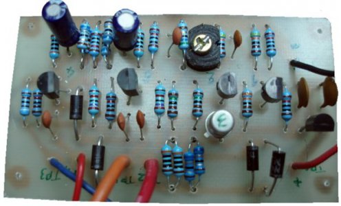
Enclosure construction
Instead of using a readymade enclosure or building one from bend metal sheet, I tried a new approach based on thermo bending plastic:
For raw material I used plastic from an old computer CRT screen
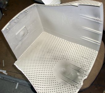
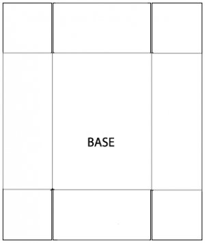
To make the shape needed I have cut a wooden block the size of the needed box,
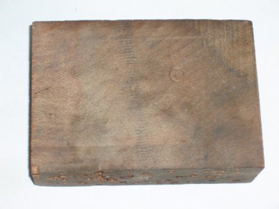
Then I have cut a plastic sheet from the side of the box according to dimensions needed
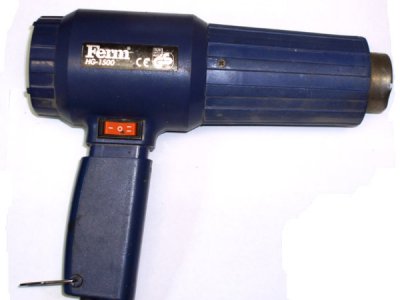
I have put the plastic sheet on the block and heated it with my heating gun
As the plastic heated to a pliable forming temperature, using wood and gloves I formed it into the shape of the wood and trimmed to create the top of the box
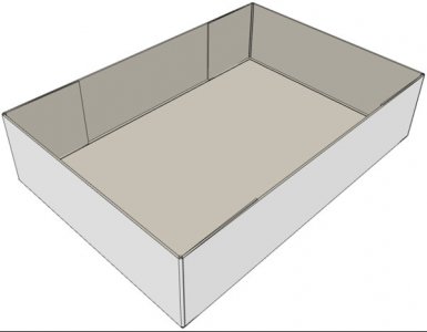
Was the process success?
…nearly.. As it was my first trial to that procedure I learned that you need some sort of applying a pressure on all sides to keep the form until plastic cools down. I had success in 4 out of 5 sides. You can see the left side of the enclosure to be a little curved
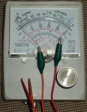
The final box, although not perfect, is still ok to be used as enclosure for the meter
After a few labels my new tool is ready to use.
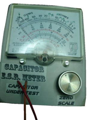
Calibration
The only calibration the meter needs is simple.
1. Zero the meter by turning the 10k trimmer after connecting together the 2 crocodile clips.
2. Using the crocodile clips connect a few resistors of a known value and mark the value on the scale.
I have used a combination of some 0.15 Ohm resistors and marked the scale
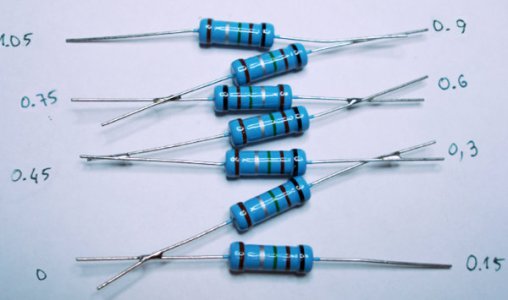
I need to make a nice printout though and replace the original… as it looks very messy now.
Making measurements
After calibration I tested the meter using a known bad capacitor
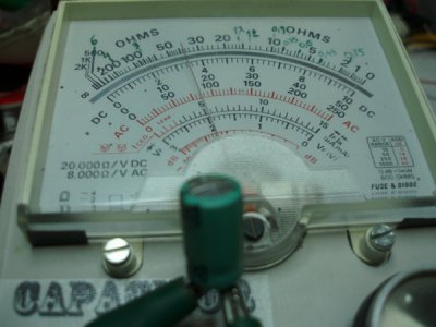
And a known good one
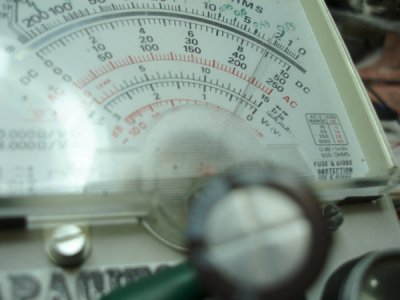
The meter WORKS I'm happy!!!
Parts list
Part Value
C2 1.5nf
C3 10nf
C4,6 2.2uf/1uF el
C5,7,8 22nf
C9,10 0.1uf
D1,2 1N4004, or 1N2007
D3,4 1N5711or 1N34A, or OA91
IC1 7805T 78L05T (smaller)
Q1,2,4,5 2N2222 or 2n3904
Q3 2N2907 or 2n3906
R2,3,13,22 10k
R4 3.3k
R5,7 4.7k
R6,11 1.5k
R8 150R
R10 3R
R12 30R
R14 27k
R15,19 330R
R16,20 33R
R17,18 1.2k
R21 27k
R24* 12k
VR23 10k TRIM 6MM The 10K pot is place in series with the 50uA meter
If you have a 100uA meter, the total resistance, meter + resistor plus + (pot resistance / 2) should be equal to about 7.5 k Ohms.
*Note R24 is typically 12k Ohms but may need some adjustment. The 10K pot is place in series with the 50uA meter.
A larger schematic:
Thanks for reading.
Petros

That “later” came a few days ago when I needed a way to test Equivalent Series Resistance (ESR) of some electrolytic capacitors that looked good but die quickly.
Let’s take the story from the beginning!
The need to test capacitors’ Equivalent Series Resistance (ESR) increases daily because more electrolytic capacitors are used into circuits where resistance causes problems. Especially now that switch-mode power supplies (SMPS's) have been commonly used in domestic PCs and TV's for a decade or so, one of the most likely components to fail is the humble electrolytic capacitor.
Why not use a readily available capacitor meter? Because when electrolytic capacitors go faulty, they normally don't lose their capacitance significantly (as is normally assumed). Rather their equivalent series resistance (ESR) goes high.
A capacitor ESR tester tests for this capacitor failure, reading the series resistance of the capacitor directly in ohms.
I will give some brief answers to some basic questions about ESR.
Why not buy a commercial one? Well, apart from the price, that is quite high for a meter like that, mainly for the joy of “making” it!
1. What Is ESR?
Every capacitor has some ESR. ESR is the electrical resistances in series with the capacitor plates. Electrolytic capacitors depend on a water-based electrolytic, soaked into a strip of porous material between the aluminum foil plates, to complete the outer electrical connection to the aluminum oxide dielectric coating on the anode foil.

The electrolytic has electrical resistance which, along with the (negligible) resistance of the connecting leads and aluminum foil plates, forms the capacitors equivalent series resistance.
Normally the ESR has a very low value, which stays that way for many years unless the rubber seal is defective or the electrolytic is heated (the service life of electrolytic caps is approximately halved for every 10 degrees C increase in temperature). Then the electrolytics water component gradually dries out and the ESR increases with time.
As a result, the electrolytic gradually acts more and more like a capacitor with its own internal series resistor.
2. What Causes ESR To Change?
The most Common cause of high ESR is drying of the electrolyte solution. Drying occurs because of the evaporation of water in the electrolyte solution. The solution soaks the paper spacer between the two aluminum plates. The water carries the electrical charge from the negative aluminum plate to the surface of the insulating oxide on the positive plate. The oxide forms the capacitor’s dielectric and the negative charge on the surface of the oxide forms the negative capacitor plate. As the water evaporates, the electrical resistance increases.
Manufacturers provide tables with acceptable ESR values for their capacitors.

3. Why is ESR so difficult to detect?
The circuits that measure ESR must be able to ignore other capacitor parameters, including the capacitive reactance at a given frequency. It would be handy if we could just reach inside with a DC ohmmeter and measure the resistance in series with each metal plate. We can’t do that, because the capacitor blocks any attempt to measure with DC. Therefore, we must use an AC signal to isolate a DC failure mode.
The ESR meter described here is used to measure the series resistance of a capacitor either in-circuit or out-of circuit. As ERS is usually expressed as the maximum value at around 100 KHz for the tantalum and aluminum electrolytic capacitors, the meter uses this frequency to measure the impedance of the capacitor. For Capacitors larger than a few uF this is approximately equal to the ESR.
Meter description
This is a simple ESR meter designed by eevblog member Jay_Diddy_B. (https://www.eevblog.com/forum/projects/5-transistor-esr-meter-design/msg171364/#msg171364) It uses a 50 uA linear meter (one from an old multimeter fits the bill nicely) and a handful of easy to find components:
5 general purpose transistors, a 5V regulator, 5 diodes, a few capacitors and a dozen resistors. The only critical parts, apart from the meter, are the two diodes D3 and D4. Diodes should be small signal Schottky 1N5711 or 1N34A, Ge diodes, OA91 or similar. Common diodes like BAT54 have too much capacitance and they will affect the meter scale (i.e. make it less sensitive). The circuit takes its power from any DC source 9 to 15V, you can omit the regulator and have the circuit work directly from 3 or 4 AA batteries.
Schematic

The maximum voltage on the capacitor under test is 100mV. This allows for in-circuit capacitor testing. ESR meter do not need to be precise, it most instances a bad capacitor will have an ESR many times that of a good one.
Construction
All components except meter and 10 k potentiometer are mounted on a single sided printed circuit board. Figure 1 shows the component side of the PCB and the position of each component, at the bottom you can see the copper track pattern.

PCB construction
The problem most people have is getting the track pattern off the paper and onto the board and still maintaining a reasonable amount of accuracy. To make the PCB you will need a piece of single sided board, a printout of the copper track pattern, PCB pen and etch. The board was made using the following method:
Print the copper track pattern on paper. Clean the PCB with wire wool and then wash it in hot soapy water. Fix the printed paper on the copper side of the PCB and drill all holes. When finished remove the tracing paper and start to re-draw the pattern onto the board with a PCB pen (or your wife’s red nail varnish). Be careful when drawing the the lines as shown on the layout. My wife’s red varnish was used on the prototype board but other colors should work just as well.
When the varnish has dried etch the board following the instructions supplied with the acid. You will know when the acid is working as the un-covered copper starts to turn pink and slowly dissolves. When the board is etched rinse it, dry it, clean off the varnish with acetone, then re-drill the holes (as they are filled with varnish as well) then clean it with wire wool and the pcb is ready.

Enclosure construction
Instead of using a readymade enclosure or building one from bend metal sheet, I tried a new approach based on thermo bending plastic:
For raw material I used plastic from an old computer CRT screen

To make the shape needed I have cut a wooden block the size of the needed box,

Then I have cut a plastic sheet from the side of the box according to dimensions needed

I have put the plastic sheet on the block and heated it with my heating gun

As the plastic heated to a pliable forming temperature, using wood and gloves I formed it into the shape of the wood and trimmed to create the top of the box

Was the process success?
…nearly.. As it was my first trial to that procedure I learned that you need some sort of applying a pressure on all sides to keep the form until plastic cools down. I had success in 4 out of 5 sides. You can see the left side of the enclosure to be a little curved

The final box, although not perfect, is still ok to be used as enclosure for the meter

After a few labels my new tool is ready to use.

Calibration
The only calibration the meter needs is simple.
1. Zero the meter by turning the 10k trimmer after connecting together the 2 crocodile clips.
2. Using the crocodile clips connect a few resistors of a known value and mark the value on the scale.
I have used a combination of some 0.15 Ohm resistors and marked the scale

I need to make a nice printout though and replace the original… as it looks very messy now.
Making measurements
After calibration I tested the meter using a known bad capacitor

And a known good one

The meter WORKS I'm happy!!!
Parts list
Part Value
C2 1.5nf
C3 10nf
C4,6 2.2uf/1uF el
C5,7,8 22nf
C9,10 0.1uf
D1,2 1N4004, or 1N2007
D3,4 1N5711or 1N34A, or OA91
IC1 7805T 78L05T (smaller)
Q1,2,4,5 2N2222 or 2n3904
Q3 2N2907 or 2n3906
R2,3,13,22 10k
R4 3.3k
R5,7 4.7k
R6,11 1.5k
R8 150R
R10 3R
R12 30R
R14 27k
R15,19 330R
R16,20 33R
R17,18 1.2k
R21 27k
R24* 12k
VR23 10k TRIM 6MM The 10K pot is place in series with the 50uA meter
If you have a 100uA meter, the total resistance, meter + resistor plus + (pot resistance / 2) should be equal to about 7.5 k Ohms.
*Note R24 is typically 12k Ohms but may need some adjustment. The 10K pot is place in series with the 50uA meter.
A larger schematic:

Thanks for reading.
Petros
Last edited:
