
- Joined
- Jul 27, 2021
- Messages
- 221
Greetings,
I am putting the finishing touches on an X Axis Powerfeed for my RF-31 clone. I chose to use a NEMA23 stepper and control it with an Arduino Uno and a stepper driver. I suppose I could have made my life easier using a DC motor, but I figured I would give a stepper a go if nothing else to get a bit of experience setting these large steppers up.
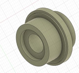
I took the handwheel and X Axis coupler off the right end of the table. The coupler is secured with a tapered pin to the shaft and has a recess on the table side of the coupler to contain the thrust bearings in there. I turned a chunk of 2" round aluminum I had on hand down to the appropriate dimensions and left a recessed pocket on the table end just like the original part. I drilled a through hold in the right location and the new coupler fits exactly like the old one, containing the thrust bearings properly. I attached an image of the CAD model, although the final version was modified a bit to accommodate the pulley.
I then bored out a pulley to be a near press fit on the new coupler and put it into position on the coupler. It had set screws as well so I used those too.
I then made a couple of brackets out of scrap aluminum I had on hand with one bolted to the back of the table (with adjustment slots) and the other bolted perpendicular to that one also with slots for belt tensioning. I made this second one too long as I missed a measurement somehow but the slots work - there is just a bit more overhang than I would prefer. It is very rigidly mounted.
For the controls I chose to use a two direction momentary joystick off Amazon along with a potentiometer to vary the speed. Power for the stepper driver comes from a 24V power supply that I also connected to a buck converter to supply 9V to the Arduino Uno. I am using all inputs as pullup inputs so there is no voltage on the controls to speak of. The direction switches are normally open and the limits switches are normally closed. The latter is just in case a wire gets severed or something.
I wrestled with the code for a while before I got it to function correctly. I am not using any stepper libraries - I just have the pulse pin go high and low separated by delays that are based on the potentiometer. Getting all of the parameters right for this took some time, but it is in a pretty good spot. I have the driver set to disable the stepper unless the toggle is activated. This way I can manually make slow, fine adjustments with the power off the stepper coils. I am not too worried about sending voltage back into the driver as I will only be making slow, fine adjustments. The powerfeed can move quite slowly so I can get to pretty precise locations with the stepper.
I put my 8" rotary table and a vise on the table to approximate the maximum weight I am likely to have on the mill and the stepper moves it just fine. You can ramp from very, very slow to a very nice clip using the potentiometer. The one challenge with this version of the code is that there is no acceleration built into the code - it goes right to the speed you are telling it to from the pot. If the pot is on the highest speed, the stepper will stall when you hit the toggle switch. I just back the pot down a bit and it works fine. I can twist that pot as fast as I can with no stall, so I am working on getting some acceleration code built into a revised version (version 12?).
I 3D printed a box for the controls that has two layers - one for the stepper driver and another for the Arduino, buck converter, and a breadboard. I used a breadboard for convenience's sake while testing and figured why not just use it in the final version? If I get creative I may design a custom PCB for this and have it built, but that is a lot of work...
I also 3D printed the little bracket for the controls. I will see how this holds up over time and may replace it.
The cost was reasonable. About $35 for the stepper, $28 for the driver, and $22 for the power supply. The toggle was $10 and I had the Arduino, breadboard, buck converter, and pot laying around. I think you could buy everything for under $100, add some wire, and you are off to the races.
Anyway, here are a couple of videos showing the control box and the unit in operation. If anyone has some acceleration code for Arduino I am all ears! Comments or suggestions are appreciated.
Tom
I am putting the finishing touches on an X Axis Powerfeed for my RF-31 clone. I chose to use a NEMA23 stepper and control it with an Arduino Uno and a stepper driver. I suppose I could have made my life easier using a DC motor, but I figured I would give a stepper a go if nothing else to get a bit of experience setting these large steppers up.
I took the handwheel and X Axis coupler off the right end of the table. The coupler is secured with a tapered pin to the shaft and has a recess on the table side of the coupler to contain the thrust bearings in there. I turned a chunk of 2" round aluminum I had on hand down to the appropriate dimensions and left a recessed pocket on the table end just like the original part. I drilled a through hold in the right location and the new coupler fits exactly like the old one, containing the thrust bearings properly. I attached an image of the CAD model, although the final version was modified a bit to accommodate the pulley.
I then bored out a pulley to be a near press fit on the new coupler and put it into position on the coupler. It had set screws as well so I used those too.
I then made a couple of brackets out of scrap aluminum I had on hand with one bolted to the back of the table (with adjustment slots) and the other bolted perpendicular to that one also with slots for belt tensioning. I made this second one too long as I missed a measurement somehow but the slots work - there is just a bit more overhang than I would prefer. It is very rigidly mounted.
For the controls I chose to use a two direction momentary joystick off Amazon along with a potentiometer to vary the speed. Power for the stepper driver comes from a 24V power supply that I also connected to a buck converter to supply 9V to the Arduino Uno. I am using all inputs as pullup inputs so there is no voltage on the controls to speak of. The direction switches are normally open and the limits switches are normally closed. The latter is just in case a wire gets severed or something.
I wrestled with the code for a while before I got it to function correctly. I am not using any stepper libraries - I just have the pulse pin go high and low separated by delays that are based on the potentiometer. Getting all of the parameters right for this took some time, but it is in a pretty good spot. I have the driver set to disable the stepper unless the toggle is activated. This way I can manually make slow, fine adjustments with the power off the stepper coils. I am not too worried about sending voltage back into the driver as I will only be making slow, fine adjustments. The powerfeed can move quite slowly so I can get to pretty precise locations with the stepper.
I put my 8" rotary table and a vise on the table to approximate the maximum weight I am likely to have on the mill and the stepper moves it just fine. You can ramp from very, very slow to a very nice clip using the potentiometer. The one challenge with this version of the code is that there is no acceleration built into the code - it goes right to the speed you are telling it to from the pot. If the pot is on the highest speed, the stepper will stall when you hit the toggle switch. I just back the pot down a bit and it works fine. I can twist that pot as fast as I can with no stall, so I am working on getting some acceleration code built into a revised version (version 12?).
I 3D printed a box for the controls that has two layers - one for the stepper driver and another for the Arduino, buck converter, and a breadboard. I used a breadboard for convenience's sake while testing and figured why not just use it in the final version? If I get creative I may design a custom PCB for this and have it built, but that is a lot of work...
I also 3D printed the little bracket for the controls. I will see how this holds up over time and may replace it.
The cost was reasonable. About $35 for the stepper, $28 for the driver, and $22 for the power supply. The toggle was $10 and I had the Arduino, breadboard, buck converter, and pot laying around. I think you could buy everything for under $100, add some wire, and you are off to the races.
Anyway, here are a couple of videos showing the control box and the unit in operation. If anyone has some acceleration code for Arduino I am all ears! Comments or suggestions are appreciated.
Tom
Attachments
Last edited: