Gear pressure angle question

I think he measered it roughly. He is a farmer not machinist remember :big grin:
 
:p. If the center distance cant be adjusted, can you adjust the OD or is that taboo
 
:p. If the center distance cant be adjusted, can you adjust the OD or is that taboo
Maybe by a thou or two. You need to know the center distance measurement accurately to a thousandth of an inch, two max or you stand a really good chance of making gears that won't turn because the teeth are clashing or they are so far apart they will strip.

Milling gear cutters cut the tooth recess they don't cut the OD, so you can make the OD anything you want, but that don't mean the gears will be right or work on any center distance.
 
Yes, taboo for the most part, I understand that pinions of low numbers of teeth are sometimes enlarged to reduce undercutting of the teeth, which would be less of a problem with 20 degree teeth than 14 1/2 PA. I saw mention of it on Machinery's handbook once upon a time, but know less than a little about it. having the center distance larger than it is supposed to be makes for noisy operation and high wear.
 
A accurate measurement of the center distance is necessary to know where we are going with all this.
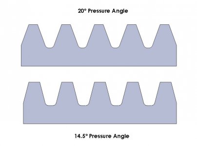
 
Here is a comparison of gear racks for a 20º P.A. and a 14.5º P.A. . All gears with the same modulus/diametral pitch and pressure angle will mesh with a rack with the same parameters.
Gear Pressure Angle Comparison.JPG

The drawings were made in SolidWorks using the defining equations for a gear rack. The sketches were done parametrically,based on the pressure angle and modulus of the gear. Changing those two parameters to suit will permit making a full sized drawing of the rack for any desired modulus or diametral pitch.

There are several ways in which this can be put to use. For metric gears, the vertical distance at the left or right of the rack is equal to twice the modulus. For inch gears, the modulus is equal to 25.4/diametral pitch so a 16 D.P. gear would have a modulus of 1.5875.

Scaling the drawing accordingly, a to-size drawing of the particular modulus and P.A. of interest can be printed out for use as gage. A more permanent gage could be made by gluing the drawing to a piece of backing and cutting the outline, The solid model or a dxf drawing can be furnished, from which the drawings can be scaled up/down as required
 
Back
Top