New VN 12, a few questions

tekym

H-M Supporter - Gold Member
H-M Supporter Gold Member
Joined
Apr 13, 2022
Messages
13
I just arranged to buy my first mill, a WWII-era VN 12 in really good shape, I'm going back to pick it up in a couple weeks. I took with me today a large set, possibly complete, of VN C collets, 2 overarm support brackets, a 12" VN C arbor, and some horizontal cutters.

Questions I haven't found answers to anywhere else:
- What's the clamping range of a VN C collet? I know ER collets, for example, can each clamp within a range of sizes. I'm guessing due to the time period and design of them this may not be true of the C system, but I wanted to ask. This set at a quick run through appears to be a nearly complete set from 1/16" to 5/8" by 64ths (32 collets total, I'm going to clean them up and organize them tonight), and I'm unlikely ever to use a 17/64" etc. collet in the first place, but nice to have a full set in case.
- Will a 2-ton engine hoist's legs clear the base sufficiently to lift it/set it back down? The seller is going to borrow a friend's forklift to load it for me, but an engine hoist is my current option for unloading. Next option is to build a gantry crane like I've seen photos of here, but if I can get away without that, that'd be nice.
- I'm going to hunt down a dividing head eventually, but I've seen a couple versions in the VN literature. They made one that swiveled horizontally, and one that swiveled vertically - what's the difference? I see all the B&S copies and most of the other old iron versions I've seen online swivel vertically, but what are the differences of ability between them?
- I'd like to eventually find a universal head attachment, but I also envision making a new one - is there anyone out there who has one who has taken/would be willing to take measurements sufficient to make an exploded diagram?
 
In a milling machine, there is little to no need for 32nd or 64th collets, in fact only the end mill body sizes would ever see use.
 
That makes sense, I assume the many 64ths collets are for drilling, predrilling for tapped holes, etc. since there's no quill and no easy drill chuck. Nice to have them in case I ever need them.

Turns out the set is unfortunately missing 1/8", 3/8", and 1/2", except for one that's still in the mill (I'm guessing it's the 1/2", but I didn't think to check when I looked at it) , and the 1/4" collet is present but a bit chewed up. I suppose it'd be easy enough to get some 1/64" shim stock and wrap a cutter in it before sticking it in the next size up collet, or turn some reducers on my lathe, short of making new collets myself.
 
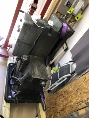
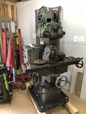
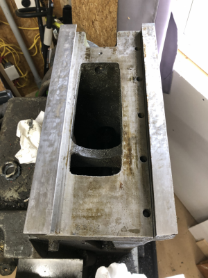
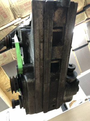
My new VN12 is acquired and in place and in process with the (heavy duty) cleaning. Here's the story so far:

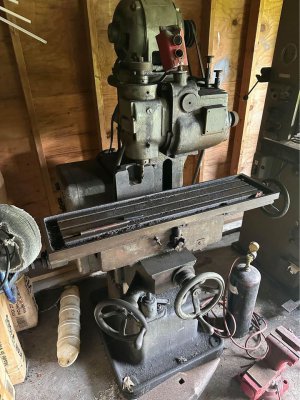
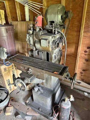
I found this machine on Facebook Marketplace a couple hours away (I'm in MD, it was in DE), the seller had originally asked $1200 but dropped it to $900 after sitting for about a week with no takers, I guess. The listing had just two photos and a basic description that it came with a "full collet set" and was mechanically sound and functional except for the power switch that had gotten bumped with a forklift.

FB1.jpgFB2.jpg

No notes that it had the overarm support, or the motor belt cover, or the table stops, etc. I asked about the overarm support bracket and belt cover, and had to provide some photos for the seller to match them (he hadn't had the machine long and wasn't super familiar with it). Turns out it had those, so I drove out to see it, and ended up buying it. I drive a small hatchback, so I couldn't take it with me that day, but I took the collet set, the overarm support (it actually has two, one broken and one intact), and the belt cover, and arranged to come back with a truck the next weekend.

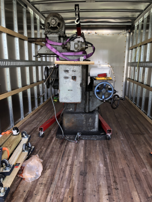
Next weekend, the seller had hired a tow truck with a boom to help load it, and with a great deal of finesse on the part of the tow guy (low ceiling height for lifting), got it onto the truck, strapped down to within an inch of its life, and drove home.

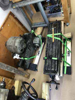
Upon getting home, I hoped to get it taken apart with my engine hoist enough to use the lift gate to get all the pieces down onto the ground, then quickly take the truck back before they closed at 430pm. That didn't happen, not even close, I ended up having to take all weekend and had to get help from friends to get it off the truck, across my driveway/yard, and into my shop.


IMG_4746.pngIMG_4757.pngIMG_4758.png

After some cleaning and inspection of the sliding surfaces I had taken apart (ram and knee/saddle only), I got it reassembled and not taking up quite so much space in my already overfull and incomplete shop. (Plus bonus cheap dividing head that I picked up a couple weeks later, which needs a thorough breakdown and cleaning as it currently doesn't move.)

IMG_4834.png

I got it put up on some 4x4 beams with heavy duty casters under them for ease of movement, but that turned out to be a mistake (the beams were bending) and I took it off those once I picked up a pallet jack. I so wish I had had the pallet jack when I brought the mill home, it has come in so handy for that and other things too.

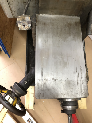
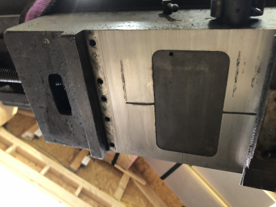
The knee and saddle have some pretty good scoring in a couple places, I guess some chips got caught at some point over the last 80 years and dragged. The ram slide is (unsurprisingly, as it's not a frequently sliding surface) in better shape, showing remnants of the original flaking and planer marks on the underside of the ram.

IMG_4788.pngIMG_4792.pngIMG_4811.pngIMG_4818.png

I haven't yet tried to take the table off the saddle, as I understand that to be a more involved process than I've done so far. I have a lot of cleaning to do, as the entire thing is covered in a thick layer of I think soot, plus the ordinary oils and a ton of chips. It's slow going, but I'm making progress on that front. I'm also working on rewiring the external wiring, as the original armored cable is both filthy and difficult to clean and also smashed up a bit in places. I had to cut the wiring to the motor to get the ram off, and reconnecting to the motor has been gross, as there's I guess dielectric grease or something under the tape wrapping, leaking out everywhere. I don't yet know if the motors work, but I assume they do based on the seller's description and their easy turning under hand power. I got an American Rotary DIY panel to go with a spare 5HP 3-phase motor I had to make a phase converter.

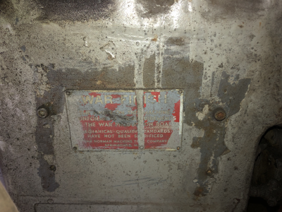
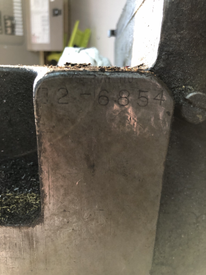
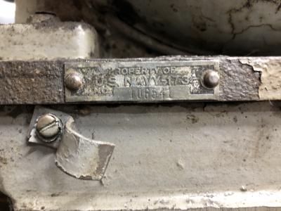
As part of the cleaning, I've discovered some things about this particular mill. It feels like it's in really good shape, all the axes move smoothly and without very much backlash (I'm going to add a DRO anyway). The serial number is 12-6854, which dates to 1942, probably early in the year, and that plus the War Finish tag means it's a war baby. I also discovered under a heavy layer of paint a US Navy tag, US Navy-173, which based on a quick googling sounds like this mill may have been on the USS Eldridge. I had previously thought this mill may have been a USAF mill, as most of the collets that came with it have "USAF" engraved on them. I guess maybe it got transferred, or some prior owner collected them separately.

IMG_4689.pngIMG_4786.pngIMG_5021.png

I also found stamped into the back of the ram a date, 12-22-1942 (the dashes are actually 1s turned sideways, so probably not original), and I'm not positive what that refers to exactly. The serial number points to early 1942, maybe February, and the USS Eldridge launched in the middle of 1943, so, unclear.

My plan right now is to get the mill cleaned, take the table off the saddle and clean/inspect, and strip and repaint everything, as the paint is in terrible condition and is flaking off all over the place. I haven't taken any indicators to anything yet to see how much wear is in the sliding surfaces, but as of right now my intent is to use it as is, and maybe in 20 years when it hits its 100th birthday I'll do a full restore, re-scrape, etc.

This is my first mill, so I've got a lot to learn. Looking forward to it, it's going to be fun.
 
As for accessories:

In addition to the not quite full collet set (described above), the mill came with a 12" horizontal arbor. That is similarly filthy, and I haven't yet taken it apart to see if it's 7/8" or 1".

The fixed table stops were missing when I picked it up, but when I started cleaning the chips out of the table, I found one of the two buried in the chips. I'm replicating them in Fusion 360 and 3d printing a replacement. I'll eventually mill a steel replacement, once I get running. (I also don't yet have a vise, or a hold down kit, or anything else, so I've got to do that too). I'll post the STL once I get it done so other people can use it, since the fixed table stops are apparently so commonly removed.

I can't find it now, but I recall seeing a post where someone had made a casting model for a new tool tray - any idea who/where that was? This mill is missing its tool tray, for some odd reason (no idea why someone would take it off in the first place).

As part of my disassembly/etc., I want to catalog what all the various parts are. We (collectively) have parts diagrams with part numbers available, but no descriptions for what each part is/screw threads/etc.

I also just found on Ebay a VN 10" horizontal swivel dividing head, with all its parts and accessories, including a few collets/toolholders/arbors. I don't have that yet, I'm working out shipping with the seller, probably via Fastenal's Blue Line Freight store-to-store shipping service. I had to jump on that due to its completeness and not-absurd price. I want to make gears, so I'm looking forward to that.

Also also, I picked up a Bridgeport M head, which I'm going to adapt to the overarm bar for easier drilling and boring.

I'd like to someday find a Universal Head and a Slotting Head, but given their rarity I'd like to know - is there anyone out there who has either of these and would be willing to take measurements/make a drawing so I can make a copy?
 
Last edited:
It's been a while, but I'm still in process with cleaning and reassembling. I'm also getting closer to having my shop finished, working on the ceiling insulation the past few days, just got my minisplit set up and running last week so I don't have to work in the cold.

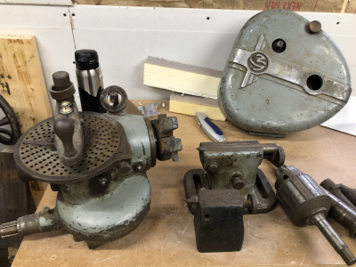
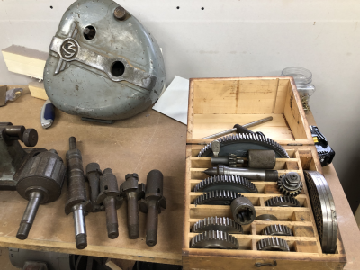
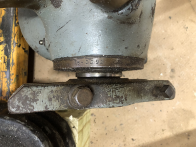
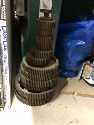
The VN 10" horizontal swivel dividing head I mentioned in my last post arrived and is in excellent condition. It came with the original matching VN tailstock, as well as a smaller Hardinge tailstock, plus the gear train case, two different sets of gears for it, and an assortment of third party-made collets and toolholders. There's a few more things than I included in the photos below even, it was quite a haul. The dividing head's serial number is prefixed with a 16-, and that plus the gear train case attachment method makes me pretty sure it's of a newer vintage than my 1942 mill.

dividing head w acc.pngdividing head acc.pngdividing head serial.pngdividing head 2nd gear set.png

The Bridgeport M head is currently sitting disassembled for cleaning and repair, as one of the studs that holds the motor in place broke out of its spot in the belt/pulley body. I'm going to get some JB Weld epoxy and see if that will work to fill in the broken spot. I also need to track down a pulley for the motor - the seller couldn't find it, so the head only has one of the two pulleys it needs to function.

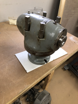
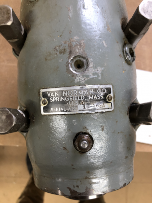
Additionally, I picked up a (also No. 16-era) universal head from a seller on Practical Machinist. The bolt pattern on it doesn't match the accessory mounting hole pattern on the #12 head, so I'm going to make an adapter. I'll probably also have to make the drive collet to extend it to add the thickness of the adapter, but hey, I have a dividing head now so I can do that. Likewise, I'll need to make a collet drawtube for it, as the seller didn't have one for it.

universal head 1.pnguniversal head serial.png

One question/problem I'm running into now that I could use some insight for - as I'm trying to clean/etc., I am 100% unable to get the drawtube and collet with an endmill in it apart, it's still the same way it was when I bought the mill over the summer. Does anyone have any ideas for how to loosen it without destroying the spindle bearings? I can't get it to budge either way. I've got an adjustable wrench on the hex on the end of the drawtube, and a hook spanner in the hole in the side of the spindle to hold it still. Putting a socket on my impact driver also doesn't help. I can't think of some way to heat the drawtube to expand/loosen it. Any ideas?
 
Last edited:
All good on getting the drawtube loose, just needed a cheater bar to apply more torque. I discovered upon finally removing the collet that the collet key is gone, which probably explains why the drawtube was wrenched down so tight. I've got some replacement keystock and a new roll pin on their way from McMaster Carr.

In other news, I actually fired up the mill for the first time yesterday. I made sure I had finished rewiring the parts I needed to (I ran new wire to the spindle motor and a new top start/stop switch since the original armored cable and switch were trashed), turned my phase converter on, and started it up in a low gear. Everything seemed to be okay, except that both the spindle and the feed motors were turning backwards from what I think they ought to be based on the switch (easy enough to fix).

When I flipped the spindle switch to off, let it spin down, and then switched it into reverse, that tripped the breaker. Damn. So something is wrong. I don't think it's anything I did, as I replaced wiring 1-to-1 vs what was there before as far as I'm aware.

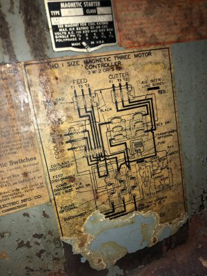
I need some help deciphering/diagnosing the problem. My mill is wired as shown in this post/diagram. I probed various points with a multimeter set to continuity testing, and have no idea what I'm seeing. Given that flipping the spindle direction is what tripped the breaker, I started there, positing that maybe the switch is defective. But there's continuity across all 6 connections (3 phases) regardless of how the switch is set. I didn't disconnect the switch from everything else, so maybe that's where I'm seeing continuity, but I need a second opinion. What should I be looking at to diagnose this?
I would clean all the contacts. They are all coated in silver and may look black. You'll need some very fine Emory cloth. I was able to closely balance my voltages by doing this. Its a pain but every contact should be cleaned if there is any carbon from the arcing of the contacts is present or there is corrosion on the silver.

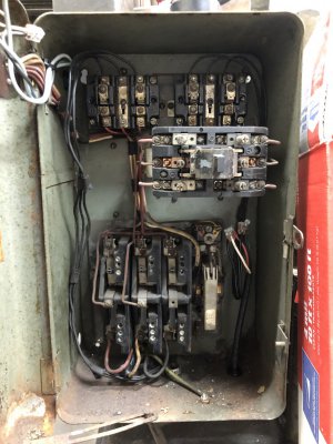
Tripping the breaker is something I wouldn't know where to look but is it the magnetic coil lever tripping or your panel breaker tripping? These have two 6AMP heaters that are supposed to de-energize the 4 wire coil (below and to the right of the reversing switch) and release the contacts when tripped.

Can you take a picture of electrical box inside?

I would take voltage measurements of the contacts before and after switches and of the wires going to motors. This will give you an idea if the contacts have a higher resistance through them. You'll need to test with motor running and measure T1-T2, T2-T3 and T1-T3. Report back your line voltage incoming into the box then your line voltages going to the motor.

And be careful in there.
 
Last edited:
The contacts in mine are all brass, I think. Cleaning up the electrical box generally is on my list of things to do though, there has clearly been some rodent activity at some point in the past. All the wiring appears to be as indicated on the diagram, so I don't think that's an issue.

The trip was in the panel breaker in the wall, not anything on the machine itself. And it tripped instantly when I flipped the spindle switch from off to Left, so that says to me a short somewhere.

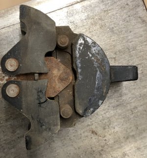
I pulled the switch out to isolate it and test it independently. The back side of it is potted, but there are 3 wires poking through, two red (probably the direction switch lines) and one yellow (T3 I assume). I'm going to take some resistance readings and see what's up. If this is fine, next on my list I'll pull out the overload relays and do the same. Ultimately I guess this electrical setup isn't actually that complicated, so I hope I can track down this issue without too much difficulty, just need to find the time.
 

Attachments

  • IMG_5514.JPG
    IMG_5514.JPG
    443.3 KB · Views: 5
  • IMG_5509.jpg
    IMG_5509.jpg
    290.6 KB · Views: 5
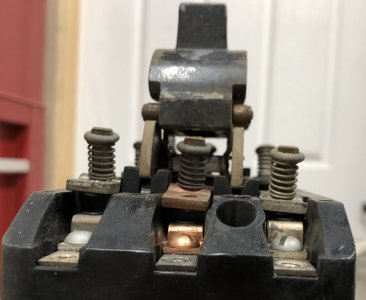
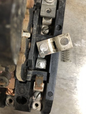
I found the problem. Turns out my suspicion was correct, it was a short and it happened in the switch.

I was probing the connections with a multimeter to look for continuity/resistance and found that two of the terminals that should switch were connected in both L and R. I was flipping the switch over in my hands looking for anything to explain why, when I noticed this:

IMG_5529.JPG

The contact plates aren't all at the same level. The lower one on the right there is the one that shorted out:

IMG_5528.JPG

The problem seems to be that the "arms" of the switch that push the contactor plates down are stiff on one side and don't rotate up and out of the way to disconnect things; you can see in the first photo that the one on the right is sitting lower than the one on the left, preventing the plates from lifting up enough. I spent a little while trying to clean the pivot point last night, it's a little better, but next I'm going to dig up some electrical-safe lube I have somewhere and see if that'll help.
 

Attachments

  • IMG_5530.JPG
    IMG_5530.JPG
    317.1 KB · Views: 2
Back
Top