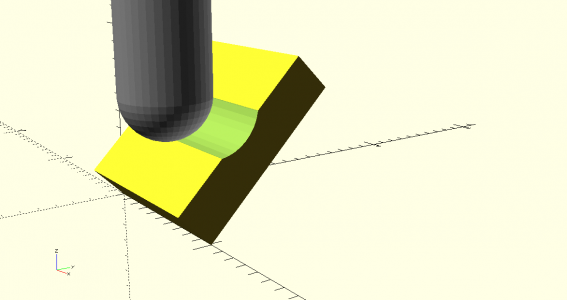
Trying to get a consistent surface finish with a ball nose end mill.

Parlo

Registered
Registered
Joined
Feb 21, 2022
Messages
771
Machining slots with a ball nose end mill usually gives a different finish on each side of the slot. One side is conventionally milled & the other climb milled. Also the cutting speed approaches zero towards the centre where there is often very little chip clearance. Has anyone tilted the head of the machine to eliminate these issues?
I tried the theory out on my CNC but had to mill uphill as I could not tilt the head, it should yield the same result.
 
Instead of tilting the column, tilt the work a bit. If milling along the X axis, rotate the work around X. No uphill milling needed. Feasibility depends on the depth of the slot you need and size of the piece you want to mill.

A horizontal mill would do the trick, too. Same caveats apply :).

The first approach would complicate things in terms of getting the slot accurately positioned. A horizontal mill would need a special cutter. It's always something, eh?
 
"Instead of tilting the column, tilt the work a bit. If milling along the X axis, rotate the work around X. No uphill milling needed. Feasibility depends on the depth of the slot you need and size of the piece you want to mill."

The demonstration tilted the work around the Y axis so the toolpath had to be uphill to keep the depth constant. Are you suggesting tilting the work front to back i.e. rotating around the X axis? I can't see how a full depth slot could be acheived without using the centre of the cutter at zero cutting speed or eliminate the climb/conventional finishes or cutting a true radius one one side & a deeper one on the other.
Could you possibly post a sketch so I can understand your principle better.

The original post referred only to a ball nose cutter, I understand other cutters on other machines will solve the problems better.
 
Yes, rotate the work around X AND move the work along X to cut (the same relationship would work by rotating around Y and moving along Y). As I mentioned earlier, feasibility depends on the depth of the slot you want to cut. A reduced-shank ball-nose cutter would get you deeper. Only you know what you need.....

It's unfortunate you can't tilt the head of your machine. That capability really would address your issues.
I see. You mean rotate the work as it is cutting. I assumed you meant rotate the work at an angle then clamp it, like I did in the video. I did assume that there were only 3 axes to use.
Perhaps I should have just tilted the head on my Bridgeport which would have probably illustrated the concept clearer. I rarely move my Bridgeport head out of tram so I simulated it on my CNC mill.
The last time I tilted the head was to demonstrate my own formula for simulating curved slots which approximates a curve through 3 points if you don't own the precise size ball nose cutter.
Here is the video for reference.
Hehe. This illustrates the pitfalls of assuming one thing that ain't true. In this case, I mean something I didn't understand about your question. I DID mean a rigidly-mounted workpiece, the idea of rotating the work WHILE milling didn't occur to me. That might do the job.....but certainly would make for an "interesting" setup. I'd rather put up with having to re-tram my mill!
 
Hehe. This illustrates the pitfalls of assuming one thing that ain't true. In this case, I mean something I didn't understand about your question. I DID mean a rigidly-mounted workpiece, the idea of rotating the work WHILE milling didn't occur to me. That might do the job.....but certainly would make for an "interesting" setup. I'd rather put up with having to re-tram my mill!
I guess that's why we have drawings. I still don't understand what you meant in post #2. :confused:
 
Maybe the image below will make things clearer?? The work is moved toward/away from the viewpoint.


tilted work study.png
 
Back
Top