Worm Gear Adventure

epanzella

Active User
Registered
Joined
Apr 8, 2013
Messages
1,980
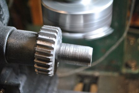
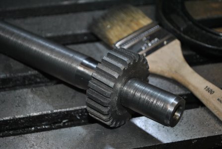
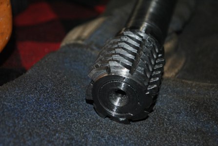
I 'm making a 24 to 1 worm gear transmission for a future project. This is my first time making worm gears. I started by making a horizontal fly cutter with the 4 tpi tooth profile to cut the teeth on the mill. With a cast iron blank this was the mother of all interrupted cuts and my spin indexer was not up to it. Next I tried making a million passes using a slitting saw but could not get the involute right nor duplicate the constant spiral of the worm. Finally I did what I should have done on day one. I made a hob and hardened it. This worked pretty slick after I gashed the blank with a slitting saw and followed up with the fly cutter. The teeth were about 75% formed and the hob finished the job in 15 minutes. I've included some video of cutting the blank with the hob and also running the worm and worm gear that will be meshed together in the final product. They running here at 600 rpm.
 

Attachments

  • GASHING GEAR.JPG
    GASHING GEAR.JPG
    513.9 KB · Views: 34
  • GEAR GASHED ONLY.JPG
    GEAR GASHED ONLY.JPG
    375 KB · Views: 34
  • HOB A.JPG
    HOB A.JPG
    415.7 KB · Views: 34
  • HOBBING GEAR.MOV
    23.6 MB
  • RUNNING GEAR.MOV
    30.9 MB
I've made many spurs and some bevels.
Not yet made a worm or helical, but am setting up to do so.
Thank you for your encouragement.

Daryl
MN
 
Just reading the calculations is hard ;)
 
What did you make the hob out of? And is something else driving the worm wheel while it's being hobbed, or is it self-driving?

Nice work regardless...
 
What did you make the hob out of? And is something else driving the worm wheel while it's being hobbed, or is it self-driving?

Nice work regardless...
The hob is O1 tool steel machined then heat treated. The worm wheel is gashed first with a slitting saw so that the hob can drive it while teeth are formed.
 
Last edited:
Back
Top