-
Welcome back Guest! Did you know you can mentor other members here at H-M? If not, please check out our Relaunch of Hobby Machinist Mentoring Program!
You are using an out of date browser. It may not display this or other websites correctly.
You should upgrade or use an alternative browser.
You should upgrade or use an alternative browser.
Dovetail myth regarding pin dimensions.
- Thread starter Parlo
- Start date
- Joined
- Sep 17, 2020
- Messages
- 74
OK, so thanks for that.
This is my take away.
The whole "pins" thing is an esoteric way for someone to show off they passed a trig, class and trying to make me look stupid?
Cause that is about the way I feel like right now.
This is my take away.
The whole "pins" thing is an esoteric way for someone to show off they passed a trig, class and trying to make me look stupid?
Cause that is about the way I feel like right now.
- Joined
- Dec 18, 2019
- Messages
- 6,593
Don't feel bad about this. I (many moons ago) did pass trig (barely), but I still find this hard to comprehend. That being said, I was able to figure out using some dowels so I could match up a dovetail to my Quick Change Tool Post.OK, so thanks for that.
This is my take away.
The whole "pins" thing is an esoteric way for someone to show off they passed a trig, class and trying to make me look stupid?
Cause that is about the way I feel like right now.
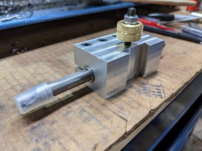
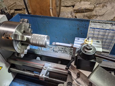
Go easy at it, give yourself some margin, and sneak up to the final dimension. The boring bar holder I made fits the QCTP, so I'm happy. Just be careful in your final cut, as it is real easy to have that dovetail be a tiny bit too big. It will fit fine, but the handle on the QCTP will rotate too far.
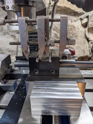
I clamped the dowels because I couldn't get anything to stand still, and then I measured them (outside to outside).

Then I cut the dovetail in the 7075 aluminum until I got the same measurements. Was not as difficult as I thought it would be.


Came out pretty well considering I had no experience, and really didn't know what to do. Unlike a lot of people here, I'm still learning as I go along! I left the brass part large, as it looked nice and it made it easier to use. Designed the holder before I knew CAD. Pretty much cardboard engineering.
- Joined
- Sep 17, 2020
- Messages
- 74
Please don't misunderstand me. I greatly appreciate all the effort going into explaining this to me.
However, while I understand the HOW this is done, It's the WHY this is done? I figure there is something critical I am missing. A LOT of effort has gone into this method to acquire these dimensions. I am trying to justify in my mind the cost of getting the proper sized pins, Clamps, etc. when simply knowing the throat size and depth of cut will do the exact same thing. No special tools. Just a good set of calipers and a bit of thought.
That is of course unless your trying for .00001" accuracy, in which case I can't even afford a BIT that accurate!! let alone the entire tools set.
By the way, your first set of drawings opened just fine for me.
Thanks again! Much appericate the effort.
b
- Joined
- Sep 17, 2020
- Messages
- 74
SAD but that is funny to me!
I worked with a shop for a few years and thought I knew their work, if it wasn't critical I didn't put tolerances on the print, Couple of thou. one way or the other was no big deal on a lot of the stuff I did. One day they made me two parts that were supposed to fit together and standing in the shop I tried, and they didn't even come CLOSE to fitting. "well you didn't put any tolerance on the drawings so this is what you got! Well make it again for another $500.00. Found a new shop after that, and was always careful to put tolerances on EVERYTHING. Cooperate force me to go back to them at one point. I had them build me a sheet metal door. No big +/- 1/8" would have been fine. Set a tolerance of .1 as that is what I had decided I would use as a standard for non critical parts. Came back 10.5 INCHES out of tolerance on the holes!!!! When I pointed this out, they insisted on wanting to make me pay for a whole new door! Let purchasing deal with them after that! I wouldn't go in there and found another shop. Only went in there 2 more times and each was to help out a fellow tech explain to them what he wanted as they couldn't understand what he was trying to say!
Fond (if you will) memories
- Joined
- Feb 1, 2015
- Messages
- 9,672
In addition as a means of communicating design intent, a drawing is a contract. If a dimension isn't specified, you have no legal recourse if something doesn't meet your need.
Drawings usually have a box tolerance where the default tolerances for dimensions are specified. These tolerances are the minimum. If you want a tighter tolerance for a particular dimension, it must be specified on the drawing. Even without a specified tolerance, the location and size of every feature must be specified. The draftsman has the responsibility of determining how to dimension a drawing to properly convey design intent. For example if you are drilling twenty holes in a row, spaced .1" apart, with a location specified as +/- .005" and the separation between each hole is dimensioned as .100 +/- .005, in a worst case scenario, the twentieth hole could be off by .1". A better way to dimension the features would be to dimension each as a distance from a reference datum. That way, each hole can only be off by +/.005" from its design position. Another pitfall is over dimensioning. In the above example. if a reference datum is used to establish the position of each hole to +/-.005" and the separation between adjacent holes is also dimensioned as +/-.005", a conflict arises and a good machinist will come back to the designer/draftsman and ask for a clarification.
Drawings usually have a box tolerance where the default tolerances for dimensions are specified. These tolerances are the minimum. If you want a tighter tolerance for a particular dimension, it must be specified on the drawing. Even without a specified tolerance, the location and size of every feature must be specified. The draftsman has the responsibility of determining how to dimension a drawing to properly convey design intent. For example if you are drilling twenty holes in a row, spaced .1" apart, with a location specified as +/- .005" and the separation between each hole is dimensioned as .100 +/- .005, in a worst case scenario, the twentieth hole could be off by .1". A better way to dimension the features would be to dimension each as a distance from a reference datum. That way, each hole can only be off by +/.005" from its design position. Another pitfall is over dimensioning. In the above example. if a reference datum is used to establish the position of each hole to +/-.005" and the separation between adjacent holes is also dimensioned as +/-.005", a conflict arises and a good machinist will come back to the designer/draftsman and ask for a clarification.
- Joined
- Feb 21, 2022
- Messages
- 786
The latest drawing ( dovetail cutter offset ) clearly shows that simply offsetting the Y axis by the cutter diameter either side does not produce a mating part. This shows that some sort of reference dimension is required.Please don't misunderstand me. I greatly appreciate all the effort going into explaining this to me.
However, while I understand the HOW this is done, It's the WHY this is done? I figure there is something critical I am missing. A LOT of effort has gone into this method to acquire these dimensions. I am trying to justify in my mind the cost of getting the proper sized pins, Clamps, etc. when simply knowing the throat size and depth of cut will do the exact same thing. No special tools. Just a good set of calipers and a bit of thought.
That is of course unless your trying for .00001" accuracy, in which case I can't even afford a BIT that accurate!! let alone the entire tools set.
By the way, your first set of drawings opened just fine for me.
Thanks again! Much appericate the effort.
b
It can be said that you can creep up with small cuts until the mating part fits but this depends on the weight and size of the parts. It also depends on whether you have the mating part to use as a gauge. This also demonstrates that there is a need for some reference dimensions & a method to measure them.
Let's go right back to basic engineering fundamentals.
Generally speaking:
Measuring over external sharp corners is always avoided, designers will ask for them to be deburred or machined off to give a flat.
Measuring over internal sharp corners is also not accurately possible with calipers and they are rarely called for as they are stress risers.
The traditional way is to give a calculated reference dimension over a given size of pins. Combined with the depth, the theoretical sharp corner positions can be measured. This technique is widely applied, not just for dovetails.
Engineering drawings need to give all the information so that parts made in different locations will always fit. When the male and female parts of a dovetail assembly are made worldwide, the machinists will need a dimension to machine the angled faces accurately. The designer will give a dimension over standard size pins for each part with the relevant fit & tolerance to ensure the parts will work as required.
If an inexperienced designer only gives the dimension over the theoretical sharp corners on the print then the machinist will need to calculate the pin dimensions themselves. Only then can the required dimension be measured, made accurately, proven and guaranteed to be passed in inspection.
I understand that the offsets can be calculated if the cutter diameter is known. Once again the cutter will need to be measured over its sharp corners. It will will have a small radius on them or some wear which makes accuracy impossible. I admit there are other methods to measure the cutter but not practical for individual machine shops to go to this trouble. There still needs to be a method and a dimension to measure the finished part to though.
So although mating parts with angles can be made to fit without any measuring, there needs to be a method for consistent manufacture and traditionally this is using common size pins. With a dovetail assembly there will always be two different dimensions over standard pins, one for the female and one for the male. The method I proposed reduces these two dimensions to one common dimension. It only works with dedicated size pins though. Luckily the pin diameter can easily be calculated as 1/3rd of the dovetail depth. This is the only calculation required. To prevent making or purchasing odd size pins I suggest that the dovetail depth is a factor of 3. For example a 12mm deep dovetail will need 4mm standard pins to give a common size for both parts. ( Formula for 60 degrees only, other ratios for different angles are on the video description ).
Hope this helps.
- Joined
- Feb 1, 2015
- Messages
- 9,672
Measuring to a feature like a virtual sharp is problematic. A machined surface is likely to have either a slight burr or, if it is remov3d, a small rounding of the edge. Furthermore, one of the mating surfaces will be an inside corner. while one can measure the outside corner and the height of the dovetail and assume that the dovetail angle is dead on to calculate the inside corner, it is not best practice.
Conversely, the distance separating two dovetail surfaces is a fairly easy measurement to make using two pins and is actually the best representation the working surface.
Conversely, the distance separating two dovetail surfaces is a fairly easy measurement to make using two pins and is actually the best representation the working surface.


