Please correct me if I am wrong

See right now it’s just going 3.5”-7”/3.5” - 7” say I wanted just this speed only all 4 pulleys are exactly the same just opposite of each other wouldn’t it be the same if I eliminated one stage

NO. To get the same speed with a single stage you would need 3.5" to a 14". That may be hard to accommodate and that is why multiple stages are used to get high reductions.
You might find this interesting
 
, if I'm understanding what I read about vfd's, lack of torque at lower rpm's is already an issue...

-Bear

As the frequency of the VFD is reduced to reduce motor speed the voltage is reduced in proportion. This is done otherwise the motor current will increase at lower frequencies and cause overheating. Another reason is that at low motor speed there is less cooling adding to a heating problem. Torque is proportional to current and so torque is not increased as speed is decreased. At low speeds our machining torque demands increase but they are not met by the VFD like they are by mechanical reduction. My approach to this problem is to fit oversize motors with VFDs. When I fitted a VFD to my Bridgeport I went to a single speed but I replaced the stock 1 hp motor with a 5 hp motor. Low speed torque is adequate and top speed has gone from 3500 to 6000 rpm.
 
Last edited:
Tony,
Your Bridgeport drive conversion is an inspiration.

One question. How did you mate the sheave to the spindle splined shaft. My thinking is to bore the sheave to fit the shaft OD (over the existing splines) and use at least one setscrew to extend into a spline groove. I'm just wondering how you chose to do it.

EDIT: Duh! The dawn broke. Set screwing the pulley to the splined shaft would have voided quill travel. I'm old enough for old-timers-disease to be an issue.
 
Last edited:
Ok I was mistaken on my thinking with rotation. But yes let me describe clearer. my motor has a 4 step pulley that drives another 4 step pulley attached to a counter shaft with a 2 step pulley driving my spindle which has obviously a two step pulley on it. Now the only 2 speeds I use are the middle speeds on the 4 step pulleys the 2 speeds on the counter shaft I never change. Basically if you have a 3 inch pulley driving a 7” pulley with a 3” pulley attached to bottom of it and that 3” pulley is driving a 7” pulley Wii it produced the same torque as a motor driving a 3” pulley to a 7” pulley driven aka spindle

Yes, you can remove the counter shaft and put it in the compartment in the base of the mill for the next guy if the two speeds you need can be had without the counter shaft. There is nothing magical about the counter shaft that it needs to be there.

I find my 3ph motors are really happy running at 80hz - 100hz... they just run REALLY smooth at those speeds and pushing them up to 120hz has never been a problem. Dropping below 30hz looses a LOT of torque, even with a vectorless VFD.
 
Last edited:
Yes, you can remove the counter shaft and put it in the compartment in the base of the mill for the next guy if the two speeds you need can be had without the counter shaft. There is nothing magical about the counter shaft that it needs to be there. You might need to flip the step pulley on the motor or on the spindle over so the diameter changes on the pulleys will be opposite of each other.

I find my 3ph motors are really happy running at 80hz - 100hz... they just run REALLY smooth at those speeds and pushing them up to 120hz has never been a problem. Dropping below 30hz looses a LOT of torque, even with a vectorless VFD.
Due to physical configuration of his machine (see the photo in reply #5), your advice about removing the countershaft is not consistent with his desire to use two RPM options via the step pulleys. The motor seems to be very near (if not directly above) the spindle.
 
Due to physical configuration of his machine (see the photo in reply #5), your advice about removing the countershaft is not consistent with his desire to use two RPM options via the step pulleys. The motor seems to be very near (if not directly above) the spindle.

Yep! That is a screwy arrangement! My mill head is arranged like a dillpress with a counter shaft in the middle. I wouldn't mess with that layout.
 
Last edited:
Tony,
Your Bridgeport drive conversion is an inspiration.

One question. How did you mate the sheave to the spindle splined shaft. My thinking is to bore the sheave to fit the shaft OD (over the existing splines) and use at least one setscrew to extend into a spline groove. I'm just wondering how you chose to do it.

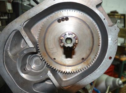
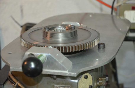
I cheated. I kept the original gear and bolted a pulley to it for the polyVee belt.

BridgePort_04.JPG

BridgePort_16.JPG

The black knob and spring etc. pushes a probe into the gear to lock it for tightening the draw bar.

BridgePort_15.JPG
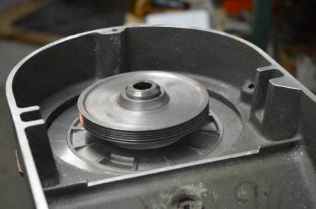
Pulley on the motor. Upsidedown photo.
 
Basically what he is saying is that he has two levels of speed reduction and he is asking if he eliminates one level, will he still get the same torque at the spindle. The simple answer is no.

A 2:1 reduction will give a 2:1 torque increase. A second 2:1 reduction will result in a 4:1 torque increase. If he added a third 2:1 speed reduction, it would multiply motor torque by 8:1...

However, by eliminating one layer of speed reduction, (which is what he wants to do), he will increase the spindle speed by 2:1 and reduce spindle torque by the same ratio.

This is why I advised him to leave it 'as is'. Even if the vfd can compensate for the doubled speed, the torque will be cut in half permanently... which, if I'm understanding what I read about vfd's, lack of torque at lower rpm's is already an issue...

-Bear
Yes winner winner you are correct and totally understand! After thinking thru it better and looking up my machinery’s handbook I absolutely need to keep the countershaft design with 2 identical belts I just don’t I just wish I could come up with a better way of tensioning the belts the way it is now the countershaft with pulleys slide back and forth on 2 1/2” rods basically like a bearing take up that tensions both identical size belts at the same time allowing the centerline of the motor and spindle to be dead on top of each other. I would like to make the pulley and counter shaft in a fixed position but dont know how I could tension the belt coming off the counter shaft to the spindle!?! I could tension the top belt via making the motor slide. Which brought me to this whole conversation of wanting to remove the counter shaft but that’s not a option now so I’ll probably just copy same design thanks for your help
 
I cheated. I kept the original gear and bolted a pulley to it for the polyVee belt.

View attachment 489135

View attachment 489136

The black knob and spring etc. pushes a probe into the gear to lock it for tightening the draw bar.

View attachment 489137
Pulley on the motor. Upsidedown photo.
Yeah I have a Webb Cham head as well i debated doing the same thing by just bolting a stapped pulley to the original variable speed pulley half until i seen how much those pulleys sell for!! But did you keep the back gear on the machine or remove it?
 
Tony,
Your Bridgeport drive conversion is an inspiration.

One question. How did you mate the sheave to the spindle splined shaft. My thinking is to bore the sheave to fit the shaft OD (over the existing splines) and use at least one setscrew to extend into a spline groove. I'm just wondering how you chose to do it.
My machine doesn’t have a drawbar or splined drive like yours it’s has this
 
Back
Top