- Joined
- Dec 3, 2020
- Messages
- 217
Late to the game here, all the cool kids have had DROs on their mills since the dawn of time. I doubt my install breaks any new ground, but I took the damn pictures so I'm gonna share 'em.
I got the cheapest scales I could find, Sino brand 5 µM "slim" glass, off ebay. The slim scales are recommended if you want to mount your Y-axis the way I did, it fits easily under the saddle. On my clone, I needed 520 mm for X, and 220 mm for Y. YMMV (your mill may vary). I'm not using any Z-axis so far, but I can add it (and/or W-axis for the quill) later if I want. The Touch DRO unit has four inputs, ready when I am.
The scales came with only one bracket each, which were useless. I made my brackets out of 1/4" thick steel because that's what I had handy. Way overkill but that's better than underkill.
The X-axis scale and read head were super easy, just drill/tap two holes in the front of the table. The threaded holes to mount the read head were already there in the saddle, they're there for the thing the travel stops bump against. Yes I lost that function, no travel stops anymore, but I'm OK with that.
Lots of people have mounted their X scale to the back of the table, but then I'd lose about an inch of Y-axis travel when the scale hits the column. I don't often use all the travel, but when you need it you NEED it.
I think there might be another option that keeps all your travel and keeps the travel stop feature, if you mount the scale to the saddle and the read head to the table, but I don't like it when the read head moves, dragging its cable back and forth. Also, keeping the opening in the scale facing down, to keep swarf out, would be tricky with that arrangement. Happy to be corrected if anyone knows an elegant way to get that done.
I used the included guard/cover on the X-axis, just because it made things line up a bit easier, but I don't think it actually does much guarding. It does make the scales less "slim" so you might consider leaving the guard off on yours. Yuriy of Touch DRO says he never uses the guards, just keep the opening facing down or away from the spray of chips and coolant.
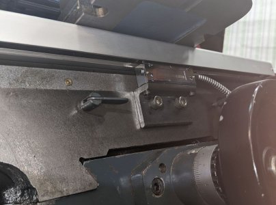
This scale is bolted to a machined surface, and I set it exactly flush with the top of the table, so when I ran a dial indicator over its full travel, it was already right on, no adjusting or shimming required.
The Y-axis was a lot more work. Here's the initial mockup, before I made brackets:
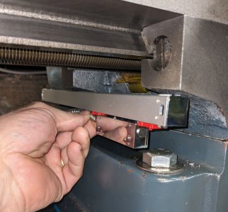
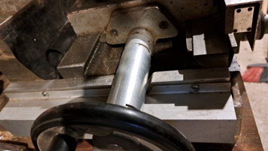
There's a machined surface on the end of the saddle, perfect for bolting the bracket to. Just a few holes in a piece of flat bar, oh and the bar needs to be "scalloped" to clear the leadscrew bearing bracket, and a scallop for the gib:
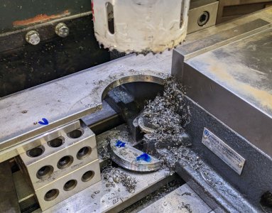
The cheap holesaw easily powered through the 1/4" stainless (free from a friend's scrap pile), even left a nice surface finish, not that it matters.
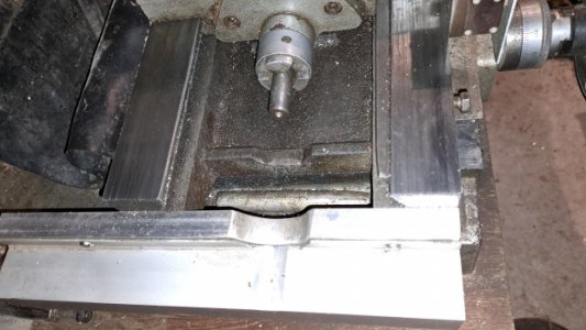
Here's one showing why it needed to be scalloped:
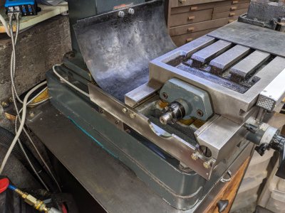
Tapping cast iron is usually drama-free, but I did use drilling and tapping guides to keep the holes "normal" (perpendicular)
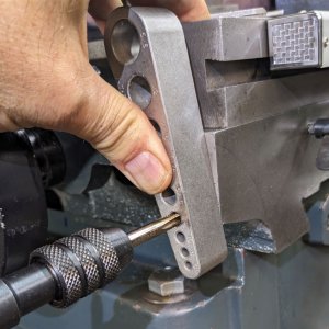
I bolted the read-head bracket to the cast base of the mill. I used a stainless angle 1/8" thick, cut out of a square tube (from the same scrap pile as the other bracket). Sawing up a square tube is not the easiest way to get some steel angle, but it saved a trip to the steel-gettin' place.
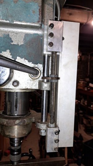
I considered two places to put it, inside (to the right) of the head, and outside (to the left). Settled on the outside because the bracket will protect the read head better from getting whacked. It's just bolted to that raised lip around the top of the base, but I did file it flat locally, so it's not bolted to paint and bondo. I spaced it further to the left than in this pic, by putting .180" spacers on the mounting bolts between the bracket and the read head. That gets the flat side of the angle bracket fully in contact with the flat top of that lip on the mill base.
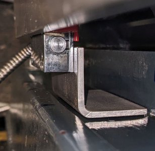
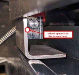
The spacers also bring the lower bracket in alignment with the upper, close to flush on the outer edge.
I ran an indicator over both brackets in both up/down and side to side directions, took a little tweaking. More work than the X-axis for sure, but this only needs to be done once.
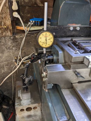
A bit awkward to get in there, needed 2" travel indicator because I needed to retract the indicator to pass over the saddle, between the front and rear measurements, but I was able to run the indicator over the full travel of the Y. I went back and forth a few times to convince myself the setup was repeatable, and it is to within the precision of this indicator. I settled for under .002" difference over the full range of travel. Someone correct me if that's not considered good enough, but I don't see any issues so far.
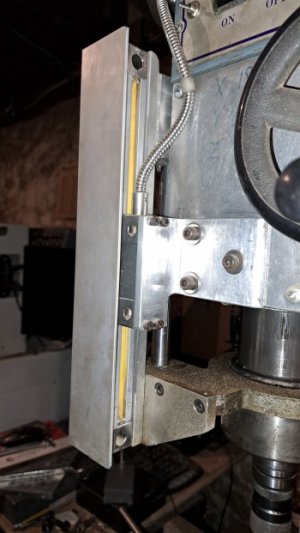
As you can see, I left guard off on this one, effectively making the scale "slimmer". It didn't look to me like the guard would really be guarding anything.
I tapped M4x0.7 holes in the 1/4" thick bracket for the scale to bolt to, but if you don't want to tap such tiny holes, you could just drill a clearance hole and use a nut on the outside. Actually the best of all would be to use a bolt whose head fits tight in the slot in the scale, so it can't rotate, then you tighten it from the outside with a nut. Normal M7 bolt heads don't fill up the slot though, they can rotate, so I would have had to make some sort of custom shim to keep the bolt heads from rotating. Would be nicer to be able to tighten it from the outside after it's all assembled, necessary for "tramming it in", but since this is a one-time task, I can live with the slightly awkward placement of the bolt head. A wrench does fit in there. Socket-head cap screws might be easier, but I didn’t have any in the right length
Well that's about all I can think of. I might be dreaming to think this write-up will actually be of use to "future generations", but I'm jazzed to have it done, and writing it up has been fun for me.
Many thanks to Yuriy at Touch DRO and to everyone else here who has supplied info, tips and inspiration.
bulgie out
I got the cheapest scales I could find, Sino brand 5 µM "slim" glass, off ebay. The slim scales are recommended if you want to mount your Y-axis the way I did, it fits easily under the saddle. On my clone, I needed 520 mm for X, and 220 mm for Y. YMMV (your mill may vary). I'm not using any Z-axis so far, but I can add it (and/or W-axis for the quill) later if I want. The Touch DRO unit has four inputs, ready when I am.
The scales came with only one bracket each, which were useless. I made my brackets out of 1/4" thick steel because that's what I had handy. Way overkill but that's better than underkill.
The X-axis scale and read head were super easy, just drill/tap two holes in the front of the table. The threaded holes to mount the read head were already there in the saddle, they're there for the thing the travel stops bump against. Yes I lost that function, no travel stops anymore, but I'm OK with that.
Lots of people have mounted their X scale to the back of the table, but then I'd lose about an inch of Y-axis travel when the scale hits the column. I don't often use all the travel, but when you need it you NEED it.
I think there might be another option that keeps all your travel and keeps the travel stop feature, if you mount the scale to the saddle and the read head to the table, but I don't like it when the read head moves, dragging its cable back and forth. Also, keeping the opening in the scale facing down, to keep swarf out, would be tricky with that arrangement. Happy to be corrected if anyone knows an elegant way to get that done.
I used the included guard/cover on the X-axis, just because it made things line up a bit easier, but I don't think it actually does much guarding. It does make the scales less "slim" so you might consider leaving the guard off on yours. Yuriy of Touch DRO says he never uses the guards, just keep the opening facing down or away from the spray of chips and coolant.

This scale is bolted to a machined surface, and I set it exactly flush with the top of the table, so when I ran a dial indicator over its full travel, it was already right on, no adjusting or shimming required.
The Y-axis was a lot more work. Here's the initial mockup, before I made brackets:

There's a machined surface on the end of the saddle, perfect for bolting the bracket to. Just a few holes in a piece of flat bar, oh and the bar needs to be "scalloped" to clear the leadscrew bearing bracket, and a scallop for the gib:

The cheap holesaw easily powered through the 1/4" stainless (free from a friend's scrap pile), even left a nice surface finish, not that it matters.
Here's one showing why it needed to be scalloped:

Tapping cast iron is usually drama-free, but I did use drilling and tapping guides to keep the holes "normal" (perpendicular)

I bolted the read-head bracket to the cast base of the mill. I used a stainless angle 1/8" thick, cut out of a square tube (from the same scrap pile as the other bracket). Sawing up a square tube is not the easiest way to get some steel angle, but it saved a trip to the steel-gettin' place.
I considered two places to put it, inside (to the right) of the head, and outside (to the left). Settled on the outside because the bracket will protect the read head better from getting whacked. It's just bolted to that raised lip around the top of the base, but I did file it flat locally, so it's not bolted to paint and bondo. I spaced it further to the left than in this pic, by putting .180" spacers on the mounting bolts between the bracket and the read head. That gets the flat side of the angle bracket fully in contact with the flat top of that lip on the mill base.


The spacers also bring the lower bracket in alignment with the upper, close to flush on the outer edge.
I ran an indicator over both brackets in both up/down and side to side directions, took a little tweaking. More work than the X-axis for sure, but this only needs to be done once.

A bit awkward to get in there, needed 2" travel indicator because I needed to retract the indicator to pass over the saddle, between the front and rear measurements, but I was able to run the indicator over the full travel of the Y. I went back and forth a few times to convince myself the setup was repeatable, and it is to within the precision of this indicator. I settled for under .002" difference over the full range of travel. Someone correct me if that's not considered good enough, but I don't see any issues so far.
As you can see, I left guard off on this one, effectively making the scale "slimmer". It didn't look to me like the guard would really be guarding anything.
I tapped M4x0.7 holes in the 1/4" thick bracket for the scale to bolt to, but if you don't want to tap such tiny holes, you could just drill a clearance hole and use a nut on the outside. Actually the best of all would be to use a bolt whose head fits tight in the slot in the scale, so it can't rotate, then you tighten it from the outside with a nut. Normal M7 bolt heads don't fill up the slot though, they can rotate, so I would have had to make some sort of custom shim to keep the bolt heads from rotating. Would be nicer to be able to tighten it from the outside after it's all assembled, necessary for "tramming it in", but since this is a one-time task, I can live with the slightly awkward placement of the bolt head. A wrench does fit in there. Socket-head cap screws might be easier, but I didn’t have any in the right length
Well that's about all I can think of. I might be dreaming to think this write-up will actually be of use to "future generations", but I'm jazzed to have it done, and writing it up has been fun for me.
Many thanks to Yuriy at Touch DRO and to everyone else here who has supplied info, tips and inspiration.
bulgie out
Last edited:

