- Joined
- Jun 26, 2014
- Messages
- 619
Well in the middle of a job today the collet holder on my mill detached from the spindle - luckily with just a thud onto the table and not sending it flying across the room. Looks like I didn't secure a grub screw sufficiently when I put it was restoring it, I had tried to remove the collet holder previously but couldn't get it off and had give up and just left it.
So anyway, now that it is off I have the opportunity to change it.
(The collets that it uses seem to be some proprietary type as I cant match them to any standard size so I'm stuck with the limited sizes that came with the mill (6, 10, 12 & 16mm) and making sleeves for any other size needed, plus they are a right pita to remove. They jam in almost flush with the holder and you end up having to 'tap' the endmill until they loosen and release. I have already snapped one carbide endmill when it was particularly stubborn to remove. I had resorted to using an ER collet holder with a 16mm straight shaft installed into the original 16mm collet and holder to make it easier to use.)
The spindle left on the machine is 25mm diameter and has about 10mm protruding from the quill.
The original collet holder seems to be a shrink fit into a larger Ring (that's what I'll call it for lake of a better term) that has a 25mm hole at the other end (with a grub screw) that attaches to the spindle.
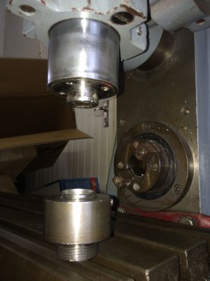
Spindle and Ring/Collet Holder - the top of the Ring has a fillet on the top ID which extends into the quill section and may be some sort of spindle grease control

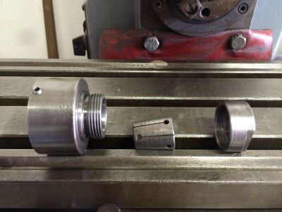
Ring/Collet Holder, Collet and Retaining Nut

My plan/thoughts are to:
1. remove the old Collet Holder from the Ring (may need heat as a couple of sharp taps hasn't budged it)
2. bore out the Ring to a shrink fit of the OD of a ER32 Collet Holder
3. shrink it onto the ER32 Collet holder with the shaft cut off it - may also add a grub screw for safety
4. reinstall it on the spindle
This assumes the outside of the ER32 Collet holder is concentric to the taper which I will have to check first.
Questions are:
Is there a trick to keeping the collet holder perfectly aligned to the spindle when installing it?
How are they attached on other machines, I don't have a lot of experience of different mills.
Is there a better way I should be approaching attaching a new collet holder to the spindle?
Any suggestions/recommendation/observation greatly appreciated. This is not something I have every done before and a see a large number of opportunities to end up with a collet holder that has horrendous run out if it doesn't all work out.
btw Mill is a CME F900 (Spanish manufacturer) horizontal mill with a separate vertical mill head .
So anyway, now that it is off I have the opportunity to change it.
(The collets that it uses seem to be some proprietary type as I cant match them to any standard size so I'm stuck with the limited sizes that came with the mill (6, 10, 12 & 16mm) and making sleeves for any other size needed, plus they are a right pita to remove. They jam in almost flush with the holder and you end up having to 'tap' the endmill until they loosen and release. I have already snapped one carbide endmill when it was particularly stubborn to remove. I had resorted to using an ER collet holder with a 16mm straight shaft installed into the original 16mm collet and holder to make it easier to use.)
The spindle left on the machine is 25mm diameter and has about 10mm protruding from the quill.
The original collet holder seems to be a shrink fit into a larger Ring (that's what I'll call it for lake of a better term) that has a 25mm hole at the other end (with a grub screw) that attaches to the spindle.
Spindle and Ring/Collet Holder - the top of the Ring has a fillet on the top ID which extends into the quill section and may be some sort of spindle grease control

Ring/Collet Holder, Collet and Retaining Nut

My plan/thoughts are to:
1. remove the old Collet Holder from the Ring (may need heat as a couple of sharp taps hasn't budged it)
2. bore out the Ring to a shrink fit of the OD of a ER32 Collet Holder
3. shrink it onto the ER32 Collet holder with the shaft cut off it - may also add a grub screw for safety
4. reinstall it on the spindle
This assumes the outside of the ER32 Collet holder is concentric to the taper which I will have to check first.
Questions are:
Is there a trick to keeping the collet holder perfectly aligned to the spindle when installing it?
How are they attached on other machines, I don't have a lot of experience of different mills.
Is there a better way I should be approaching attaching a new collet holder to the spindle?
Any suggestions/recommendation/observation greatly appreciated. This is not something I have every done before and a see a large number of opportunities to end up with a collet holder that has horrendous run out if it doesn't all work out.
btw Mill is a CME F900 (Spanish manufacturer) horizontal mill with a separate vertical mill head .


