Is This A Static Converter?

Copy: Gut
I'll look for a guide to building one.

Thank you,
Daryl
MN


Sent from my iPhone using Tapatalk
 
the square d switches used, are rated for 600v,
the control voltage is 240v- the capacitor will not increase the control voltage:)
a capacitor can't hold a charge greater than the applied voltage
 
the control voltage is 240v- the capacitor will not increase the control voltage:)
a capacitor can't hold a charge greater than the applied voltage

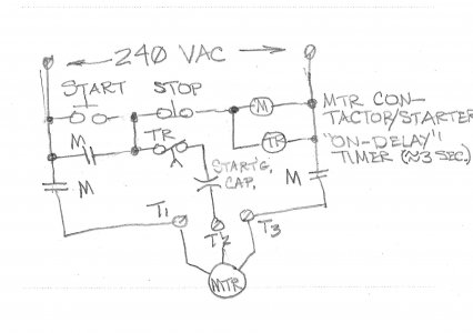
A capacitor can't exceed its applied voltage but its applied voltage can easily exceed 240V if it's connected in series with a motor winding while starting it. So it's a good idea to connect a timer or relay to the cap rather than just the push button. Here's a really quick & rough sketch of how I'd wire the controls. Note that this doesn't show any fusing or overload relays.

Phase_conv.jpg
 
All, Thanks for all the help.
Ulmadoc is putting together a care package for the saw.
Additionally, I've got some vintage mills I'll be tearing down and scraping in as needed. With a goal of reselling. I'm hoping to sell them with appropriately sized RPC or worst case statics if that's what buyers would like. I believe that 3ph is a major reason that people are afraid of vintage iron. However, I want to make sure I know what I'm doing!
And yes I've got a couple 1750rpm 3ph motors hanging around with 1-5hp motors. As well as some vintage magnetic starters.

Wire addict: what does "M" and "TR" mean in the diagram?

Is a relay an electronic switch? What do they actually do?
It's my understanding that capacitors hold onto the electricity until its reached a threshold. Then it's released. Does the relay trigger the release creating an impulse timed between the other two impulses.
Or is it a constant flow of electricity, like a garden hose.

And how does a 3ph motor generate the 3leg in a RPC?

I'm hoping to take the time to do more reading on the net and within the HM threads. However, all the threads and lit assumes basic knowledge. Of which I currently have only gaps.

Daryl
MN
 
A capacitor can't exceed its applied voltage but its applied voltage can easily exceed 240V if it's connected in series with a motor winding while starting it. So it's a good idea to connect a timer or relay to the cap rather than just the push button. Here's a really quick & rough sketch of how I'd wire the controls. Note that this doesn't show any fusing or overload relays.

Can you explain how the applied voltage will increase when you connect the capacitor in series?
 
On the right side of the sketch I wrote a 1-word description of what "M" & "TR" do; M is the motor starter or contactor coil & TR is the timer coil. & TR is usually a pneumatic timer with an air bleed adjustment which controls the time delay or the time delay can be done electronically, either by counting AC pulses or by charging or discharging a capacitor. In this particular case the timer needs to be an on-delay type where the time delay occurs when the timer coil first energizes.

It's been over 40 years since my AC fundamentals class so I don't remember all the theory & even less of the math involved. Caps cause current to lead the voltage by up to 90 degrees because maximum current through them occurs at maximum voltage & when they're fully discharged so they appear as a short across the voltage source. As they charge the current inrush decreases & the voltage across them increases, however, as the AC voltage crosses zero & reverses polarity, it, & the current discharges the capacitor & then begins to charges it in the opposite direction. Note that the phase shift created here is never over 90 degrees & 3-phase power is 120 degrees so this isn't a perfect solution but it works adequately.

And, no, unfortunately I can't explain how or why the voltage across an inductor or cap in an AC series circuit differ or exceed the applied voltage anymore [I was afraid someone would ask me this!] but I do remember this much: in an L-C series circuit the current through both is equal although the voltages can be different; in an L-C parallel circuit the voltage across both devices is equal but the currents through each can differ. And at resonance I think I recall that voltages are equal across both devices in a series circuit & currents are likewise equal through both devices in a parallel circuit. Hope this helps.
 
Back
Top