1340GT lathe is now alive, thanks to this community!

I planned for it when I built the base so that it slides in and out on these pieces of angle iron. The bottom of the pan clears the top US General tool box by about 1/2":
IMG_4279.JPG
 
@skcncx

Very nice looking set up. Putting the electronics in the tool box is a nice approach!

You have room in the box with the VFD to add a braking resistor if you want. For our lathe work the commercially available, big, bulky braking resistor that most folks use is just not needed! The duty factor for our lathe braking is so low. You can get by with a small home made one like I put into my conversion as it never even gets warm, let alone hot! In fact, in terms of power dissipation my simple design is over kill. See the photos I posted 8a, 8c, and 9a. There is also a drawing of it in the write up, Figure 6 of Part 2. Another drawing, Figure 4 show how I placed the resistor next to the VFD. The actual resistor build is described on page 12. I used eight 25 Ohm, 50Watt power resistors connected in series and parallel to yield a final 50 Ohm 400watt resistance. Of course one can built for other values, but the common 25 Ohm resistors were inexpensive. The pictures and description are at:
VFD conversion using solid state electronic components.
On second thought, maybe I have some additional pictures I can post here.

For my PM1440GT conversion, I recently designed a PCB to replace the hand made point to point wiring that I had put together. I quickly got the boards back from JLCPCB.com , but have yet to solder the components in and check it out. The boards look really nice and cost ~ $26 per 5 boards which included 7 day shipping! There really was no need for this board for my machine as continues to work flawlessly, but I wanted to learn the PCB software. @ptrotter recently turned me on to the free KiCAD software. It works really well and is a complete package, schematic capture to component layout. There is also a plugin for it which does a decent job of auto-routing the wires. Turns out that jlcpcb will also stuff the board with components, but I though I would check out my pcb layout before I see how well that service might work. It probably isn't much more expensive as the compoents used are very inexpensive.

Dave L.

PS.
To get a feeling for why the commercial braking resistors are over kill for our lathes consider the energy dissipated. The worse case energy is less than the energy used by the motor to start the lathe up. Braking it to a full stop takes no more energy than to start it in the same time period! It comes up to speed in one to two seconds, but let's say three, but it is controlled by the VFD. The Power is I*V and the energy is I*V*time so worse case power from the VFD to the motor would be < 20Amp*220V*3 seconds = 4400 watts*3 seconds = 13,200 Joules, for my 3HP PM1440GT. If you have a smaller motor then it is less. But, either motor would come to this speed much faster (probably less than 1 second) if the VFD were not slowing it down via a programmed ramp profile. (My VFD profile is set to 3 seconds to ramp up and 1, or 3, seconds to brake. ) Hence, the current actually being used is much less due to this ramping. Lets say that it might only be 1/3 or about 4000 joules or even less. The motor is not very efficient during start up and most of this power is dissipated in heating the motor windings, not just in getting things to spin up to full momentum. (The motor pulls much less than this when idling as the motor, gears, chuck, work are all then moving. The continous power mostly goes to over coming friction. Only if you are cutting lots of material away does the continuous power go up. ) However, the only energy to the braking resistor is that which it takes to stop things. This is all the energy that could possibly be sent to the resistor when braking, and it is probably a lot less as a lot of the energy is dissipated in the motor and the VFD.

13,00 to 4000 Joules sounds like a lot, but think about your toaster, hand held hair dryer, or even a microwave oven. They are set up to run on 120V at 15 Amps service... or ~ 1800 watts (these are suppose to be on a 20 Amp service, but the manufacturers must design for a typical user who doesn't know any better or one who lives in an old house with old wiring). In all fairness, the wattage rating for most of these appliances are set to about 1350 to 1500 watts so that they will run on the 15 amp service without tripping a electrical breaker. So a toaster, etc is about 1500/4400 of the maximum possible power needed to start up the lathe. So how long does it take to make a piece of toast? Go make one and look in the opening and watch the heating elements/wires. They are only starting to look hot at 3 seconds. The power resistors are basically the same wire that is used as heating elements (a NiCr alloy) in a toaster, except that they are in contact with other surrounding materials (ceramics, Aluminum, etc) which have mass to hold the heat and to carry it away. So the over all temperature of the power resistors is lower, unless you leave the power on for long times. But the lathe's braking time is a small portion of the time it is being used or even starting and stopping so we say the duty factor is low.

One might ask why the commercially available braking resistors are so big and bulky. This is to get the mass up to absorb the heat that is generated in continuous operations. If you think of a very large machine running, such as a 4 or 5 foot diameter wheel of a paper in a paper mill you can see that just trying to wind or unwind such a huge mass has the motor cycling on and braking continuously. So the duty factor is closer to 100% and a bigger resistor might be needed.

The real test of effectiveness it one of operation. After I made mine I did a quick test. I started and stopped my lathe, using a typical RPM, 3 Jaw chuck, as fast as I could for 10 times. I then quickly put my thermometer (my finger) on the power resistor. I could only just barely detect that the temperature might be a little above room temperature. Certainly not hot or even vary warm.
 

Attachments

  • IMAG2513.jpg
    IMAG2513.jpg
    226.5 KB · Views: 20
  • IMAG2518.jpg
    IMAG2518.jpg
    245.2 KB · Views: 16
  • IMAG2519.jpg
    IMAG2519.jpg
    216.3 KB · Views: 19
  • IMAG2526.jpg
    IMAG2526.jpg
    286.5 KB · Views: 19
I recognize that setup... Mine is a 1236.
View attachment 470812

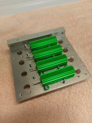
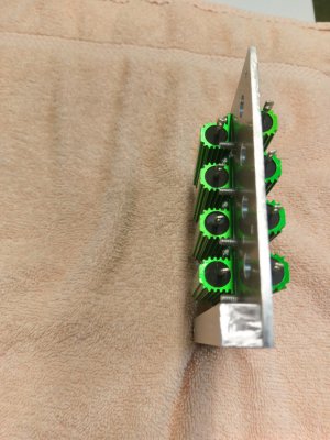
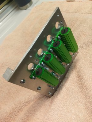
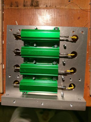
This chip/drip pan works really nicely but I still get a fair amount that rests on the C-Channel. A minor inconvenience that I was willing to accept given the rigidity of the stand and the ease of leveling the lathe due to this design. :
View attachment 470813
Nice chip pan... I think that is what i'm gonna shoot for. I ended up taking the lid off my 72" tool chest, so the tray/cavity it created is where my chip pan will go.
 
Very nice looking set up. Putting the electronics in the tool box is a nice approach!

You have room in the box with the VFD to add a braking resistor if you want.

I did install a braking resistor, 500 watt, 50 ohm, looks like a small brick. I think it was $35. I really like the braking/safety feature.

For my PM1440GT conversion, I recently designed a PCB to replace the hand made point to point wiring that I had put together. I quickly got the boards back from JLCPCB.com , but have yet to solder the components in and check it out.
Interesting. Does the PCB have a cpu on it and you plan to add code to it, like a PLC? One day I'll get into PCB design and have my own built, if nothing more than for learning/fun. I just don't have enough based knowledge nor the time to learn the PCB software, like KiCad yet.
 
  • Like
Reactions: B2
Yes, I use the e-braking all the time. The PM1440GT also comes with a foot brake for safety. Believe it or not the foot brake is considerably faster than the e-brake. In the pictures you posted I did not see the braking resistor. Where did you put it?
I also use the proximity stop as a safety feature to prevent a spindle-tool crash.

Your set up really does look nice.

Interesting. Does the PCB have a cpu on it and you plan to add code to it, like a PLC? One day I'll get into PCB design and have my own built, if nothing more than for learning/fun. I just don't have enough based knowledge nor the time to learn the PCB software, like KiCad yet.

No cpu included. The circuit board is actually pretty simple, it just an interface to all of the wires that goes from the lathe and front panel to the VFD. I think this is the same 24 volt interface function, but smaller foot print and much cheaper than the PLC. As you noted, I am not for sure why one would want to add a cpu given that the Hitachi VFD is very programmable and provides several intelligent inputs to interface with the control switches. I think the biggest issue with setting up any VFD conversion is all of the wires going to the control panel or to other parts of the lathe. By putting good 9-pin Phoenix connectors on my board I could considerably simplify this issue and make it much easier to install/remove. I also put a small circuit board in the hole behind the control panel mostly for interface connectors. I ran two 9-wire shielded cables up (8 plus shield) from the power enclosure to the control front panel. This allows one to remove the front panel by just pulling the connectors.

Looking again at your top enclosure (for the PLC) it appears to have a sufficient foot print to hold all of my conversion. I have not seen behind the control panel on your lathe so do not know how much space is in there. I assume the wires come in from the exchange gear cover area. Mine did. The front panel enclosure hole looks similar to the 1440GT, but is sloped where as the 1440GT has a flat front. If there was not enough room there might have even been a way to put the control panel, or at least the displays in your enclosure above the lathe. https://www.hobby-machinist.com/attachments/20211222_001306-jpg.389880/

My board interfaces to the lathe switches, pump motors, potentiometer, LEDs, etc. and performs the interface needed. The board uses discrete inexpensive bi-polar transistors to provide for the 24V logic interface. All of the standard functions plus are provided for. When I built my VFD conversion for my PM1440GT I built a interface/control board via point to piont wiring on a solder hole style circuit board. The pcb is only meant to replace that point to point solder board and make it easier for anyone who wants to follow my design. It provides the safety features that are standard, but maybe more. Variable motor speed via pot, read out of speed setting voltage prior to turning on the lathe (handy), interface to FW-RV-Neutral lathe switch, FW-RV jogging, Safety switches ( E-stop, Foot brake, cover interlock switches, proximity stops), e-Braking (on, off and two ramp speeds), Coolant pump interface (Off, On, automatic with FW-RV), multiple Proximity sensors and fail-safe switch, and.... The Jog feature is set up so as to operate even if the proximity sensor is turned on so that one can back away from the proximity trip point. Safety is provided by a bi-polar latch which is only enabled by putting the lathe ON-OFF-Neutral switch to the Neutral position. It is tripped off by the various safety switches and proximity sensors going active. Also provided for by the board is a 12 V regulated power, which I used at the front control panel for the spindle RPM meter and a spindle revolution counter which are displayed on the front panel. The revolution counter also performs a function of measuring the coasting revolutions occurring after a proximity stop event. So you know how far spindle etc momentum will carry the saddle beyond where the proximity stop triggered. (You usually set the trip point while the spindle is not turning so there is always a small repeatable error if you cannot predict the coast distance.)

I squeezed all of my control switches and 3 displays (programed motor speed, Spindle RPM, spindle revolution counter) into the front panel so there are no external user boxes. Also, because of my design I was able to put everything into the original lathe stand electronics enclosure which is located at the back under the motor, including the VFD, braking resistor, and a small 24V power supply. Since the coolant pump that came with the lathe runs on single phase 220V, I added a coolant solid state relay that is turned on and off via the board and the control coolant switch setting. This big SS relay, that I had laying around, is the ugliest thing about my conversion and if I had to do it over I might put the solid state relay on my pcb board. It is way over kill as it will switch 30 AM and the pump spec calls for 1 Amp.! But it is working so why change it now. The next most ugliest thing about my set up is the fan and its connection wiring that I mounted on the transparent enclosure cover. I am not even convinced that it is needed. I do like having the transparent cover as it allows me to just peek around back and see the VFD display and the colorful status LED's that I mounted on the board.

As I sit here at the screen, I cannot recall everything, so I may have left somethings out. Anyway, it is all in the posting. The posting looks long, but this is because I tried to provide all of the details for anyone who wanted to duplicate it or spring board off of it. The board functions are also describe in Part 2.

What features would you think a cpu could provide or is needed beyond those of the VFD programing? By the way, the VFD programing settings that I used are also in the Part 2 write up.

Dave L.
 
Last edited:
I just don't have enough based knowledge nor the time to learn the PCB software, like KiCad yet.
KiCad is user supported and there is a pretty easy to learn with the getting started tutorial available. It takes one through laying out for a simple switch, resistor, LED circuit. This is all I use to figure it out enough to get started. Then I jumped into doing my own circuit and found that I kept looking back at the tutorial. That worked well. You do of course have to have sufficient knowledge to design the circuits that you want. But this free CAD and the inexpensive pcb service seems to take a lot of the work out of the "hooking it up" process.

 
In the pictures you posted I did not see the braking resistor. Where did you put it?
1702925061816.png

I think this is the same 24 volt interface function, but smaller foot print and much cheaper than the PLC. As you noted, I am not for sure why one would want to add a cpu given that the Hitachi VFD is very programmable and provides several intelligent inputs to interface with the control switches.

Nice. I added two extra components to my PLC setup, that I did not need... but just the PLC itself and I/O 24v relay module was about $110. Not cheap, but not really that expensive either. Plus, I have a lot of flexibility if I want to change things in the future.

Looking again at your top enclosure (for the PLC) it appears to have a sufficient foot print to hold all of my conversion. I have not seen behind the control panel on your lathe so do not know how much space is in there. I assume the wires come in from the exchange gear cover area.

My enclosure mounted on the back of the head stock is a custom fabricated box, because of the slopping surfaces on the 1340 head stock. Live would have been easier if everything was square. It replaced the OEM electronics enclosure and extends above the headstock... it's about 9" x 9" and 7" deep.

I have about 8 cables, various multi conductor wires coming from front panel, and enclosure underneath the lathe. If I put it all together, I'd reduce that by a couple cables as the wiring from PLC to VFD would not need an external wire.


The Jog feature is set up so as to operate even if the proximity sensor is turned on so that one can back away from the proximity trip point.
I have the same setup when prox sensor is activated.

The biggest difference, is all my logic is software driven vs electronic circuitry and the various components. I would not even advocate this is a great way, but it was the route I took and could wrap my head around, plus a fun project.


One thing I would like to add is a remote frequency readout from the VFD. I'll have RPM on my DRO, but just for grins, I'd like to know the actual frequency I'm running at... being the VFD is enclose, it's not visible to read from it directly. I'm just not sure how to do it yet... not sure if I need to read and convert volts from my 2k pot on the front panel to frequency if that even can work.
 
Back
Top